
Electronic and optical systems often require a transparent window that can protect internal components without allowing excessive electromagnetic interference to pass through the enclosure.
Synthetic sapphire is well suited to harsh-environment optical windows because it offers excellent hardness, chemical resistance, temperature stability, and optical clarity. However, sapphire itself is an electrical insulator and does not provide effective electromagnetic interference shielding on its own.
To create an EMI-shielded sapphire window, the sapphire substrate must be combined with a conductive coating, metal mesh, conductive frame, or another engineered shielding structure. The final performance depends not only on the coating material but also on sheet resistance, optical transmission, grounding continuity, window dimensions, frequency range, and mechanical integration.
This guide explains the main design considerations for custom EMI-shielded sapphire windows used in industrial sensors, optical instruments, imaging systems, semiconductor equipment, aerospace electronics, and harsh-environment displays.
What Is an EMI-Shielded Sapphire Window?
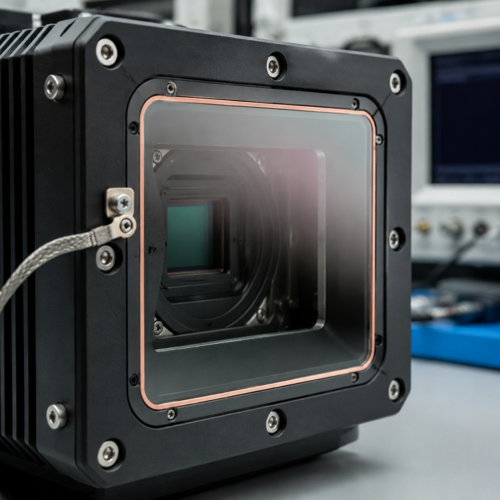
An EMI-shielded sapphire window is a transparent or partially transparent sapphire component that includes an electrically conductive layer or structure designed to reduce the transmission of electromagnetic energy.
The sapphire provides:
- Mechanical protection.
- Scratch resistance.
- Chemical durability.
- Thermal stability.
- Optical transmission.
- Dimensional rigidity.
The conductive structure provides:
- Electromagnetic shielding.
- Electrostatic charge dissipation.
- Electrical continuity with the equipment enclosure.
- Protection of sensitive electronic or optical components.
A complete EMI window is therefore a system rather than a simple piece of coated sapphire. Its performance depends on the interaction between the substrate, conductive layer, edge connection, frame, gasket, and enclosure.
Why Sapphire Alone Does Not Provide Effective EMI Shielding
Synthetic sapphire is a single-crystal form of aluminum oxide, or Al₂O₃. It has high electrical resistivity and behaves as a dielectric material under normal operating conditions.
Because it is not electrically conductive, an uncoated sapphire window cannot carry interference currents to the equipment ground. It may provide a strong physical barrier, but it creates an electromagnetic opening in an otherwise conductive enclosure.
This opening may allow electromagnetic energy to enter or escape the system.
Possible consequences include:
- Noise in imaging sensors.
- Unstable detector signals.
- Communication interference.
- Distorted measurement results.
- Electrostatic charge accumulation.
- Reduced electromagnetic compatibility.
- Failure to meet equipment-level EMC requirements.
A conductive surface must therefore be added when meaningful EMI attenuation is required.
Common EMI-Shielding Structures for Sapphire Windows
Several shielding approaches can be used depending on the required optical transmission, shielding effectiveness, operating wavelength, environmental exposure, and production volume.
Transparent Conductive Coatings
Transparent conductive coatings create a continuous electrically conductive layer across the sapphire surface.
Common coating systems include:
- Indium tin oxide, commonly known as ITO.
- Fluorine-doped tin oxide.
- Aluminum-doped zinc oxide.
- Other transparent conductive oxide coatings.
- Thin metallic or multilayer conductive films.
ITO is one of the most widely recognized options because it can provide a practical balance between visible-light transmission and electrical conductivity.
However, coating performance depends strongly on thickness, deposition process, wavelength, substrate preparation, and post-deposition treatment.
Advantages of transparent conductive coatings include:
- No visible mesh pattern.
- Uniform shielding over the clear aperture.
- Compatibility with many optical imaging systems.
- Potential electrostatic discharge function.
- Relatively low profile and weight.
Limitations may include:
- Reduced optical transmission.
- Increased reflection.
- Wavelength-dependent absorption.
- Limited flexibility.
- Possible cracking under mechanical or thermal stress.
- Sensitivity of exposed edges during assembly.
- Difficulty establishing reliable electrical contact.
Transparent conductive coatings are most appropriate when image clarity and an unobstructed optical aperture are important.
Fine Metal Mesh
A conductive metal mesh can be integrated with or positioned against the sapphire window.
Mesh materials may include:
- Stainless steel.
- Copper.
- Nickel.
- Silver-plated structures.
- Other corrosion-resistant conductive alloys.
The mesh acts as a conductive screen and can provide strong EMI performance when it is properly connected to the surrounding frame.
Advantages include:
- Low electrical resistance.
- Strong electrical connection to the enclosure.
- Potentially better shielding at demanding frequencies.
- Greater tolerance for some harsh operating environments.
- Less dependence on thin-film coating conductivity.
Limitations include:
- Visible mesh lines.
- Reduced optical transmission.
- Moiré patterns in camera-based systems.
- Diffraction and stray-light effects.
- Possible image artifacts.
- More complicated assembly.
Mesh pitch, wire diameter, open-area ratio, mesh orientation, and distance from the imaging plane all affect system performance.
Conductive Coating Combined with Metal Mesh
For demanding applications, a hybrid design can combine a transparent conductive coating with a metal mesh.
This approach may provide:
- Broader shielding performance.
- Improved grounding reliability.
- Lower total electrical resistance.
- Redundancy if one conductive structure is locally damaged.
The tradeoff is increased optical loss, greater manufacturing complexity, and higher cost.
Conductive Perimeter Metallization
Perimeter metallization is often used to connect a transparent conductive coating to a metal housing or conductive gasket.
The central clear aperture remains optically functional, while the edge contains a more conductive metal layer.
A typical construction may include:
- Sapphire substrate.
- Transparent conductive coating over the optical area.
- Conductive busbar or metalized border.
- Conductive gasket or spring contact.
- Grounded metal frame.
The perimeter connection is critical. A high-quality conductive coating provides little EMI protection if it is electrically isolated from the enclosure.
Sheet Resistance and Why It Matters
Sheet resistance is a key specification for transparent conductive coatings.
It is normally expressed in ohms per square:
The term “per square” means that the measured resistance between opposite sides of a square coating area is independent of the physical size of that square, assuming uniform coating thickness and material properties.
Lower sheet resistance generally indicates better electrical conductivity.
In EMI window design, lower sheet resistance can improve the ability of the conductive layer to carry induced currents toward the grounded frame. However, achieving lower resistance often requires a thicker conductive coating, which may reduce optical transmission.
This creates one of the central design tradeoffs:
| Coating characteristic | Typical effect |
|---|---|
| Lower sheet resistance | Usually improves electrical conductivity |
| Thicker conductive layer | May improve shielding but reduce transmission |
| Higher sheet resistance | May preserve more optical transmission but reduce shielding performance |
| Greater coating uniformity | Improves predictable electrical and optical performance |
| Poor edge contact | Can negate the benefit of a low-resistance coating |
There is no universal sheet-resistance value suitable for every EMI-shielded sapphire window.
The appropriate specification depends on:
- Required shielding effectiveness.
- Frequency range.
- Window dimensions.
- Grounding geometry.
- Optical wavelength.
- Acceptable transmission loss.
- Coating environmental durability.
- Equipment-level EMC requirements.
Sheet resistance should therefore be specified together with optical transmission and shielding requirements rather than as an isolated number.
Optical Transmission Versus Electrical Conductivity
A transparent conductive coating introduces optical losses through absorption and reflection.
As coating conductivity increases, optical transmission may decrease. The exact relationship depends on the coating material, thickness, deposition quality, wavelength, and sapphire surface condition.
Important optical parameters include:
- Average transmission over the operating wavelength.
- Minimum transmission at critical wavelengths.
- Reflection from each surface.
- Haze.
- Scattered light.
- Coating uniformity.
- Color shift.
- Wavefront distortion.
- Imaging contrast.
For camera and detector applications, total system performance matters more than a transmission value measured at only one wavelength.
A conductive coating may appear visually transparent while still affecting:
- Sensor sensitivity.
- Color reproduction.
- Low-light performance.
- Image uniformity.
- Laser power transmission.
- Detector signal-to-noise ratio.
The optical requirement should be defined across the actual operating wavelength range.
For example, a window designed for visible-light imaging should be evaluated differently from one used with ultraviolet, near-infrared, short-wave infrared, or thermal sensing equipment.
ITO and other conductive oxides may perform well in selected visible and near-infrared bands but may not be suitable across every wavelength range.
Using Anti-Reflective Coatings with EMI Shielding
Sapphire has a relatively high refractive index, so uncoated surfaces can produce significant Fresnel reflection.
An anti-reflective coating may be added to improve optical transmission. However, combining an AR coating with an electrically conductive coating requires careful layer-stack design.
Possible configurations include:
- Conductive coating on one surface and AR coating on the opposite surface.
- Conductive layer integrated into a multilayer optical coating.
- AR layers deposited above or below the conductive layer.
- Conductive coating limited to selected areas.
- Conductive coating combined with a metalized perimeter.
The coating sequence affects:
- Optical transmission.
- Sheet resistance.
- Adhesion.
- Environmental durability.
- Electrical contact.
- Cleaning resistance.
- Laser damage performance.
One common problem occurs when an electrically insulating optical layer covers the conductive coating at the perimeter. This can prevent the housing or gasket from making reliable electrical contact.
The drawing should therefore clearly define where electrical contact must remain exposed.
Grounding Design Is Essential
EMI shielding works only when the conductive window structure is properly connected to the equipment enclosure or designated electrical ground.
A floating conductive coating may redistribute electric charge, but it will not perform like a properly grounded shield.
The grounding path should be:
- Continuous.
- Low resistance.
- Mechanically stable.
- Protected from corrosion.
- Compatible with thermal cycling.
- Maintained around as much of the window perimeter as practical.
Common Grounding Methods
Grounding methods may include:
- Conductive elastomer gaskets.
- Metal spring fingers.
- Conductive adhesives.
- Solderable or brazeable perimeter metallization.
- Metal retaining frames.
- Compression contacts.
- Conductive busbars.
- Mechanical clamps with defined contact pressure.
The selected method should maintain electrical continuity throughout the equipment’s service life.
Importance of Perimeter Contact
A continuous perimeter contact is generally more effective than a single grounding point because it reduces current-path length and limits electromagnetic leakage around the window edge.
A single contact point may be acceptable for basic static-charge dissipation, but it may not provide sufficient high-frequency EMI shielding.
As frequency increases, small gaps, discontinuities, seams, and poor contacts can become important leakage paths.
The frame and gasket design should therefore be considered part of the EMI window specification.
Window Size and Shielding Performance
Window dimensions influence EMI performance.
A larger optical opening can create a greater shielding challenge than a smaller window, even when both use the same conductive coating.
Design variables include:
- Overall window dimensions.
- Clear aperture.
- Aspect ratio.
- Coating sheet resistance.
- Distance from the coating to the grounded edge.
- Number and position of electrical contacts.
- Frame conductivity.
- Joint and gasket construction.
For a large rectangular window, current may need to travel farther across the conductive coating before reaching the grounded perimeter. This can increase effective resistance and reduce shielding performance.
Potential solutions include:
- Lower-resistance coatings.
- Wider perimeter busbars.
- Multiple grounding contacts.
- Conductive mesh reinforcement.
- Segmented conductive structures.
- Continuous metal frames.
Shielding results from a small test coupon should not automatically be assumed to represent a much larger production window.
Shielding Effectiveness and Frequency Range
Shielding effectiveness is usually expressed in decibels:
Where:
- is shielding effectiveness in decibels.
- is the electric-field level without the shield.
- is the electric-field level after shielding.
A higher decibel value represents greater attenuation.
Actual performance depends on:
- Electric-field or magnetic-field conditions.
- Frequency range.
- Window size.
- Conductive-layer resistance.
- Grounding quality.
- Frame construction.
- Gasket continuity.
- Measurement method.
- Distance from the interference source.
A coating supplier’s sheet-resistance data cannot by itself guarantee the shielding effectiveness of the completed assembly.
Testing should be performed on a representative mounted window whenever the equipment must meet a defined EMC standard.
Sapphire Surface Preparation Before Coating
Coating adhesion and uniformity depend strongly on sapphire surface preparation.
Important substrate requirements may include:
- Controlled surface roughness.
- Defined scratch-dig quality.
- Thorough removal of polishing residue.
- Low particle contamination.
- No organic contamination.
- Proper edge preparation.
- Appropriate cleaning before deposition.
- Controlled handling and packaging.
Poor surface preparation may result in:
- Pinholes.
- Nonuniform resistance.
- Coating delamination.
- Increased haze.
- Local optical defects.
- Reduced environmental durability.
- Unstable electrical contact.
For high-performance imaging windows, the polished sapphire substrate should be inspected before and after coating.
Environmental and Mechanical Reliability
An EMI-shielded sapphire window may be exposed to conditions that affect the conductive coating even when the sapphire substrate remains stable.
Potential challenges include:
- Rapid temperature changes.
- High operating temperatures.
- Condensation.
- Salt or corrosive atmospheres.
- Solvents and cleaning agents.
- Mechanical abrasion.
- Vibration.
- Humidity.
- Ultraviolet exposure.
- Repeated handling.
Transparent conductive coatings are generally less scratch-resistant than the sapphire beneath them. An exposed coated surface may therefore require special handling or a protected installation orientation.
Where possible, the conductive coating can be placed on the interior side of the assembly to reduce exposure to abrasion and chemicals.
Reliability testing may include:
- Adhesion testing.
- Thermal cycling.
- Humidity exposure.
- Chemical resistance testing.
- Abrasion testing.
- Sheet-resistance mapping.
- Optical transmission measurement.
- Electrical continuity testing.
- Vibration testing.
- Shielding-effectiveness testing.
Inspection Requirements
A complete inspection plan should include optical, dimensional, electrical, and cosmetic criteria.
Recommended checks include:
Sapphire Substrate Inspection
- Outer dimensions.
- Thickness.
- Flatness.
- Parallelism.
- Surface quality.
- Clear aperture.
- Edge condition.
- Chips and cracks.
Coating Inspection
- Coating coverage.
- Sheet-resistance uniformity.
- Optical transmission.
- Haze.
- Pinholes.
- Scratches.
- Delamination.
- Color uniformity.
Electrical Inspection
- Resistance from coating to perimeter busbar.
- Continuity around the border.
- Contact resistance after mounting.
- Stability after environmental testing.
Assembly-Level Inspection
- Grounding continuity.
- Gasket compression.
- Mechanical retention.
- Optical alignment.
- Light leakage.
- EMI shielding performance.
The acceptance criteria should identify the measurement locations because both sheet resistance and transmission may vary across a large coated window.
Typical Applications
EMI-shielded sapphire windows can be considered for:
- Industrial imaging equipment.
- Semiconductor process sensors.
- Optical inspection systems.
- Harsh-environment displays.
- Laser and detector housings.
- Aerospace electronics.
- Scientific instruments.
- High-temperature camera ports.
- Chemical-processing observation systems.
- Optical communication equipment.
- Electromagnetic compatibility test systems.
- Ruggedized touch and display assemblies.
Sapphire is particularly valuable when the window must combine electromagnetic functionality with scratch resistance, chemical durability, and mechanical protection.
Information to Include in an RFQ
For an accurate custom quotation, provide:
- Sapphire window shape and dimensions.
- Thickness and thickness tolerance.
- Clear aperture.
- Sapphire crystal orientation, if required.
- Surface quality.
- Surface flatness.
- Parallelism or wedge tolerance.
- Operating wavelength range.
- Required optical transmission.
- Maximum allowable haze.
- Conductive coating type, if already specified.
- Target sheet resistance.
- Required EMI shielding effectiveness.
- Frequency range for shielding.
- AR coating requirements.
- Coated surface designation.
- Perimeter metallization or busbar requirements.
- Grounding and mounting method.
- Operating temperature.
- Environmental exposure.
- Cleaning method.
- Required testing standards.
- Prototype and production quantities.
When the coating material has not been selected, provide the optical and electrical performance requirements so the manufacturer can recommend an appropriate coating structure.
Frequently Asked Questions
Can uncoated sapphire block electromagnetic interference?
Uncoated sapphire provides mechanical and optical protection but does not offer effective conductive EMI shielding. A conductive coating, metal mesh, or another conductive structure is required.
Does lower sheet resistance always mean a better window?
Not necessarily. Lower sheet resistance can improve electrical conductivity, but it may reduce optical transmission. The correct value depends on the required shielding, wavelength range, window size, and grounding design.
Can an AR coating and an EMI coating be used together?
Yes. However, the layer sequence must be designed to preserve optical performance and electrical contact. The conductive perimeter should not be unintentionally insulated by the AR coating.
Should the conductive coating face inward or outward?
The coating is often placed on the protected interior surface to reduce abrasion and chemical exposure. The final orientation depends on optical requirements, grounding access, and environmental conditions.
Is a conductive coating sufficient without grounding?
No. A floating coating may provide limited effects, but reliable EMI shielding generally requires a continuous, low-resistance connection to the conductive enclosure or designated ground.
Conclusion
An EMI-shielded sapphire window combines the mechanical durability of synthetic sapphire with an engineered conductive layer or mesh structure.
The most important design factors are not limited to coating selection. Optical transmission, sheet resistance, window size, operating wavelength, shielding frequency, perimeter metallization, and grounding continuity must be evaluated together.
A low-resistance coating cannot provide reliable system-level shielding if its edge is poorly connected to the enclosure. Similarly, a highly conductive layer may be unsuitable if it reduces transmission below the detector’s optical requirements.
For best results, the sapphire substrate, conductive coating, optical coating, frame, gasket, and grounding structure should be designed and tested as one integrated assembly.