
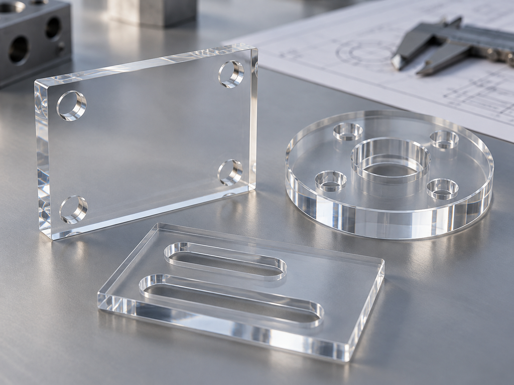
Standard round or rectangular sapphire windows are relatively straightforward to manufacture. The difficulty increases significantly when a design includes through holes, elongated slots, counterbores, stepped features, internal radii or other machined structures.
These features are increasingly common in semiconductor equipment, optical instruments, vacuum systems, laser modules, sensors and precision mechanical assemblies.
A custom sapphire component may need to perform several functions at the same time:
- Provide an optical transmission area
- Fit directly into a mechanical housing
- Allow screws, pins or sensors to pass through
- Position the window accurately
- Provide recessed mounting features
- Maintain vacuum or environmental sealing
- Survive thermal cycling and mechanical loading
Unlike metal, however, sapphire is a hard and brittle single-crystal material.
A drawing that is easy to machine in aluminum or stainless steel may become difficult, expensive or unreliable when transferred directly to sapphire.
For this reason, successful custom sapphire window design requires careful control of machining tolerances, edge geometry, feature spacing and stress concentration.
Why Machined Sapphire Windows Require Different Design Rules
Sapphire combines high hardness, excellent wear resistance, optical transparency and high compressive strength.
These properties make it highly attractive for harsh-environment windows and precision optical components.
However, sapphire has very limited plastic deformation.
Metal can locally deform around a tool or mounting point. Sapphire generally cannot. Excessive local stress can instead initiate a crack.
This changes how designers should approach:
- Hole diameter
- Hole-to-edge distance
- Slot geometry
- Internal corners
- Counterbores
- Chamfers
- Screw loading
- Dimensional tolerances
The goal is not simply to determine whether a feature can physically be machined.
The more important question is:
Can the feature be manufactured repeatedly without excessive chipping, cracking or cost, and will it remain mechanically reliable during use?
How Holes Are Made in Sapphire
Holes in sapphire are commonly produced using precision diamond tooling, grinding, ultrasonic-assisted machining or laser-assisted processes, depending on diameter, thickness, tolerance and production volume.
For many precision optical components, the final geometry still requires controlled grinding and finishing even if another process is used for rough material removal.
The most appropriate process depends on:
- Sapphire thickness
- Hole diameter
- Quantity
- Required positional tolerance
- Required edge quality
- Surface finish
- Taper requirements
- Whether the hole is inside the optical aperture
Small holes in relatively thick sapphire are considerably more difficult than large holes in a thin plate.
The ratio between hole diameter and material thickness should therefore be considered early in the design.
Through Holes in Sapphire Windows
Through holes may be required for:
- Mounting screws
- Alignment pins
- Gas passages
- Optical fibers
- Sensor access
- Mechanical locating features
The drawing should clearly specify:
- Hole diameter
- Hole position
- Positional tolerance
- Through-hole or blind-hole condition
- Entry-side chamfer
- Exit-side chamfer
- Edge-chipping requirement
A simple callout such as:
Ø3.00 THRU
may not provide enough information for a precision sapphire component.
If the hole interacts with an optical surface or sealing surface, edge condition becomes particularly important.
Why Sapphire Holes Can Chip at the Exit Edge
During drilling or grinding, the most vulnerable region is often where the tool exits the sapphire.
As the remaining material becomes very thin, the local mechanical support decreases.
This can result in:
- Small edge chips
- Shell-like fractures
- Microcracks
- Local breakout
- Irregular hole edges
The risk becomes greater when:
- The hole diameter is small
- The sapphire is thick
- The hole is close to an outer edge
- The required tolerance is very tight
- No edge chamfer is permitted
- The machining process is too aggressive
For many mechanical applications, specifying a small chamfer around the hole is beneficial.
It can remove minor machining breakout and reduce sharp stress concentrations.
Hole-to-Edge Distance Matters
A hole positioned too close to the external edge of a sapphire window can significantly reduce mechanical strength.
The remaining sapphire ligament between the hole and the outer edge carries the local load.
If this section becomes too narrow, stress concentration can increase considerably.
The risk becomes particularly important when the component is:
- Clamped
- Bolted
- Exposed to vacuum pressure
- Subjected to thermal cycling
- Installed inside vibrating equipment
There is no single universal minimum hole-to-edge distance suitable for every sapphire design.
The required distance depends on:
- Hole diameter
- Window thickness
- External geometry
- Mounting force
- Pressure differential
- Edge finish
- Expected safety factor
When space is limited, it is preferable to provide the complete assembly drawing so that the feature can be reviewed rather than specifying only an isolated sapphire part.
Slots in Sapphire Windows
Slots are useful for adjustment, cable passages, mechanical alignment and specialized optical assemblies.
Typical shapes include:
- Straight slots
- Oblong slots
- U-shaped openings
- Elongated mounting holes
- Custom cutouts
The ends of a sapphire slot should generally be radiused rather than designed as sharp internal corners.
A rounded slot distributes stress more smoothly.
A sharp rectangular slot produces much higher local stress concentration.
This is a fundamental difference between designing a feature in sapphire and designing the same feature in metal.
Avoid Sharp Internal Corners
One of the most important rules for custom sapphire machining is:
Avoid zero-radius internal corners whenever possible.
An ideal 90-degree internal corner may look simple on a CAD drawing, but it is unfavorable for both manufacturing and mechanical strength.
A small internal radius offers several advantages:
- Lower stress concentration
- Reduced crack initiation risk
- Easier machining
- More consistent edge quality
- Higher manufacturing yield
The allowable radius depends on the component dimensions and mating geometry.
If another mechanical component must fit into the slot, designers should consider modifying the mating component rather than forcing an unnecessarily sharp internal corner into the sapphire.
Counterbores in Sapphire
Counterbores are frequently requested when customers want a screw head, washer, sensor or mounting feature to sit below the external surface.
A typical sapphire counterbore may include:
- Larger upper diameter
- Smaller through-hole diameter
- Controlled recess depth
- Flat or radiused transition
Counterbores are much more challenging than simple through holes because they create a local thickness reduction.
The remaining sapphire beneath the counterbore must be thick enough to withstand:
- Machining load
- Assembly stress
- Screw load
- Pressure differential
- Thermal stress
A deep counterbore combined with a thin window can create a particularly fragile structure.
Counterbore Depth Control
For a metal component, a designer may specify a very deep counterbore with little concern.
For sapphire, the remaining wall thickness is critical.
When preparing a drawing, specify:
- Counterbore diameter
- Counterbore depth
- Through-hole diameter
- Depth tolerance
- Bottom surface requirements
- Transition radius or chamfer
- Remaining minimum thickness
If the application requires a very thin remaining section, a mechanical stress analysis may be appropriate before production.
Countersink vs Counterbore
Countersinks and counterbores should not be treated as interchangeable.
A counterbore creates a cylindrical recessed area.
A countersink creates a tapered seating surface.
Countersinks can be used for specialized mounting arrangements, but direct tightening of a metal countersunk screw against sapphire should be carefully evaluated.
The tapered contact geometry can generate high radial stresses.
In many designs, it is safer to use:
- Controlled clamping
- A compliant washer
- An elastomer
- A polymer interface
- A metal retaining structure
rather than directly applying high screw preload to brittle sapphire.
Do Not Design Sapphire as a Structural Washer
Another common design mistake is allowing a screw head to apply concentrated force directly onto sapphire.
Sapphire has high compressive strength, but localized contact forces can still generate tensile stresses and initiate cracks.
The mounting design should distribute load over a larger area.
Depending on the equipment, this may involve:
- O-rings
- Elastomer pads
- Polymer washers
- Metal retaining rings
- Controlled-torque fasteners
- Spring-loaded structures
The sapphire window should ideally be retained rather than aggressively clamped.
Edge Chipping: Cosmetic or Functional?
Not every microscopic edge chip affects component performance.
For this reason, drawings should distinguish between:
- Optical clear aperture
- Mechanical mounting region
- Sealing surface
- Non-critical external edge
A very strict cosmetic requirement applied to every edge can increase manufacturing cost substantially.
For example, a tiny chip outside the optical aperture and outside the sealing region may have no effect on the application.
In contrast, a similar defect adjacent to a mounting hole may become a mechanical concern.
The drawing should therefore define where edge quality is functionally important.
Chamfers Help Control Edge Damage
Sharp sapphire edges are highly susceptible to small chips during manufacturing, cleaning, transportation and assembly.
Chamfers are therefore commonly used around:
- Outer edges
- Through holes
- Slots
- Counterbores
- Stepped structures
A small controlled chamfer can improve handling durability and remove vulnerable sharp edges.
Instead of simply stating:
Break all edges
a precision drawing should ideally specify an acceptable chamfer range.
This makes inspection much more objective.
CNC Tolerances: Tighter Is Not Always Better
It is tempting to apply extremely tight tolerances to every dimension of a custom sapphire window.
This is rarely the most cost-effective strategy.
Tighter tolerances usually require:
- Slower machining
- Additional grinding operations
- Additional inspection
- Higher rejection rates
- More process control
As a result, manufacturing cost can rise rapidly.
The correct approach is to identify which dimensions actually control assembly or optical performance.
For example:
Critical Dimensions
These may include:
- Hole position
- Hole diameter
- Clear aperture
- Total thickness
- Counterbore depth
- Optical surface flatness
- Parallelism
Less-Critical Dimensions
These may include:
- Non-functional outer corner radius
- Cosmetic edge dimensions
- Non-mating external dimensions
Applying the same tolerance to every feature often increases cost without improving the final system.
Dimensional Tolerance and Optical Tolerance Are Different
A custom sapphire component may simultaneously have mechanical and optical requirements.
Mechanical requirements can include:
- Length
- Width
- Diameter
- Hole location
- Slot width
- Counterbore depth
Optical requirements can include:
- Flatness
- Parallelism
- Surface roughness
- Scratch-dig
- Wavefront quality
- Clear aperture
These should be specified independently.
A mechanically precise window is not automatically an optical-quality window.
Likewise, an optically polished sapphire plate may not meet precision mechanical hole-location requirements unless these are explicitly specified.
Position Tolerance for Multiple Holes
Components containing several mounting holes require careful position control.
Instead of specifying each hole only from separate linear dimensions, a datum-based drawing is often preferable.
Suitable datums may be based on:
- Outer diameter
- A reference edge
- Component center
- Main optical axis
- One or more mounting surfaces
A clear datum system reduces ambiguity between the customer’s drawing and the inspection method.
This becomes especially important when sapphire must align with:
- Metal housings
- Sensor assemblies
- Vacuum chambers
- Optical mounts
- Semiconductor equipment modules
Concentricity and Optical Axis
For circular sapphire windows, mechanical features are often referenced to the window center.
Examples include:
- Central holes
- Annular windows
- Circular counterbores
- Concentric steps
If alignment is critical, the drawing should indicate whether the concentricity requirement applies relative to:
- Outer diameter
- Clear aperture
- Optical axis
- Another machined feature
This prevents different interpretations during manufacturing.
Stress Concentration Around Machined Features
Holes and slots interrupt the continuous cross-section of the sapphire.
Under mechanical or thermal load, stress becomes concentrated near these features.
Stress concentration is especially important around:
- Sharp slot corners
- Closely spaced holes
- Thin ligaments
- Deep counterbores
- Abrupt thickness transitions
- Edge defects
The theoretical strength of sapphire can be very high, but actual component strength is strongly influenced by surface and edge defects.
This is why careful polishing, chamfering and geometry design are important for structurally loaded sapphire components.
Thermal Stress Must Also Be Considered
A sapphire component may fit into a stainless-steel, aluminum, titanium or ceramic housing.
These materials have different coefficients of thermal expansion.
If the sapphire is tightly constrained, temperature changes can produce additional mechanical stress.
This is particularly relevant in:
- Semiconductor process chambers
- High-temperature optical systems
- Laser equipment
- Aerospace sensors
- Vacuum systems
The assembly should provide sufficient accommodation for differential thermal expansion.
Precision fit does not necessarily mean zero clearance.
Holes Inside the Clear Aperture
Sometimes a design requires a hole or opening inside the optical area.
In this case, the machining edge may produce optical effects including:
- Scattering
- Stray light
- Diffraction
- Reflection
- Local wavefront disturbance
If the component is used with a laser or imaging system, the optical impact of the machined feature should be evaluated.
The designer should clearly define the usable optical region around the hole or slot.
Surface Finish Around Machined Features
A common drawing mistake is to specify optical polishing for the main faces but provide no requirement for the walls of holes or slots.
Depending on the application, the internal wall may require:
- Standard ground finish
- Fine ground finish
- Polished finish
- Controlled roughness
- Cosmetic appearance only
Fully polishing the inside of a small hole or narrow slot can substantially increase manufacturing complexity.
It should only be requested when required by the application.
Stepped Sapphire Windows
Stepped geometries can simplify mounting by integrating a mechanical locating feature directly into the sapphire.
Typical designs include:
- Reduced-diameter steps
- Annular shoulders
- Recessed optical areas
- Raised optical areas
- Integrated mounting lips
As with counterbores, abrupt transitions should be carefully reviewed.
Adding a small transition radius can reduce stress concentration and improve machining reliability.
Drawing Guidelines for Custom Sapphire Windows
A good RFQ drawing should clearly define the functional requirements without unnecessarily constraining the manufacturing process.
For sapphire windows with holes, slots or counterbores, consider specifying the following.
1. Material
Specify:
Single-Crystal Sapphire, Al₂O₃
If crystal orientation is important, specify it separately.
Examples include:
- C-plane
- A-plane
- R-plane
2. Overall Dimensions
Provide:
- Diameter
- Length
- Width
- Thickness
- Profile dimensions
3. Hole Features
Provide:
- Diameter
- Quantity
- Position
- Positional tolerance
- Through or blind
- Chamfer requirement
4. Slot Features
Provide:
- Slot width
- Slot length
- End radius
- Position
- Positional tolerance
5. Counterbores
Provide:
- Counterbore diameter
- Through-hole diameter
- Depth
- Depth tolerance
- Bottom geometry
6. Edge Treatment
Specify:
- Chamfer
- Bevel
- Radius
- Edge-chip requirement
7. Optical Surface
Specify where necessary:
- Surface roughness
- Scratch-dig
- Flatness
- Parallelism
- Wavefront requirement
8. Clear Aperture
Clearly identify which area must satisfy the optical specification.
9. Coating
Provide:
- AR coating requirement
- Operating wavelength
- Angle of incidence
- Required transmission or reflectance
10. Application Environment
Tell the supplier whether the sapphire will be used in:
- Vacuum
- Plasma
- High temperature
- High pressure
- Laser systems
- Chemical exposure
Application information often helps identify potential design risks that cannot be seen from the drawing alone.
A Practical Drawing Example
Instead of sending only:
Sapphire Plate 80 × 60 × 3 mm with 4 Holes
a more useful RFQ might specify:
Material: Optical-grade single-crystal sapphire
Overall size: 80 × 60 × 3 mm
Quantity: 20 pcs
Holes: 4 × through holes, diameter per drawing
Hole position: Referenced from defined datums
Edges: Chamfered
Optical area: Central clear aperture defined on drawing
Surface: Both major faces optically polished
Coating: Uncoated
Application: Semiconductor inspection equipment
Mounting: Four-point mechanical retention
With this information, manufacturability can be evaluated much more accurately.
Should Every Dimension Be Fully Toleranced Before RFQ?
Not necessarily.
For early-stage projects, it is often useful to send the preliminary CAD drawing and identify:
- Critical dimensions
- Functional surfaces
- Assembly requirements
- Desired optical performance
The sapphire manufacturer can then provide design-for-manufacturing feedback.
This approach can prevent a situation where an unnecessarily difficult tolerance becomes permanently embedded in the design.
Cost Drivers for Custom Machined Sapphire Windows
The cost of a custom sapphire window is influenced by much more than overall size.
Important cost drivers include:
- Sapphire blank size
- Thickness
- Number of holes
- Hole diameter
- Slot dimensions
- Counterbore depth
- Small internal radii
- Tight positional tolerance
- Edge polishing
- Optical polishing
- Surface flatness
- Coatings
- Inspection requirements
- Production quantity
A seemingly minor drawing change can sometimes significantly improve manufacturing yield and lower cost.
For example, increasing an internal corner radius or relaxing a non-critical hole tolerance may reduce machining difficulty without changing the function of the part.
Prototype Before High-Volume Production
For complex sapphire designs, prototype production is strongly recommended.
Prototype parts allow the engineering team to evaluate:
- Mechanical fit
- Hole alignment
- Edge quality
- Assembly force
- Optical performance
- Thermal behavior
- Sealing
- Stress around machined features
Design changes are much easier to implement before full production tooling and inspection procedures are finalized.
Frequently Asked Questions
Can sapphire windows be manufactured with holes?
Yes. Sapphire windows can be manufactured with through holes, precision holes and other machined openings. Feasibility depends on hole diameter, thickness, position and required tolerance.
Can sapphire be CNC machined?
Yes, but sapphire machining differs significantly from conventional metal CNC machining. Diamond grinding and other specialized precision processes are typically required because of sapphire’s extreme hardness and brittleness.
Can a sapphire window have a counterbore?
Yes. Counterbores are possible, but the remaining wall thickness, transition geometry and mechanical load must be carefully considered.
Can rectangular slots be machined into sapphire?
Yes, but sharp internal corners should generally be avoided. Rounded slot ends are preferable because they reduce stress concentration and machining risk.
What causes chipping around sapphire holes?
Chipping can result from brittle fracture during machining, particularly near the tool exit, sharp edges or insufficient material support. Proper machining parameters and edge chamfers can help control chipping.
Can screw holes be used to directly bolt sapphire to a metal housing?
They can be incorporated into the design, but high localized screw loads should be avoided. Controlled torque, washers, compliant interfaces or retaining structures may be required.
How tight can sapphire machining tolerances be?
Precision tolerances are possible, but achievable tolerance depends on feature size, material thickness, geometry, quantity and inspection method. Extremely tight tolerances should only be specified where functionally necessary.
Should hole edges be polished?
Not always. Many mechanical holes only require controlled grinding and chamfering. Polished internal walls should be specified only when optical or functional requirements justify the additional processing.
Conclusion
Custom sapphire windows with holes, slots, counterbores and stepped geometries can integrate optical and mechanical functions into a single precision component.
However, sapphire should not be designed using the same assumptions as aluminum, stainless steel or other ductile materials.
The most important considerations are:
- Avoid unnecessary sharp internal corners
- Maintain sufficient material around holes
- Control edge chipping
- Use chamfers where appropriate
- Avoid excessive localized mounting force
- Define only functionally necessary tolerances
- Separate optical specifications from mechanical specifications
- Consider thermal and mechanical stress in the complete assembly
For complex sapphire components, sending the complete drawing and application conditions before finalizing the design can significantly reduce manufacturing risk.
A design-for-manufacturing review can often identify small geometry changes that improve machining yield, reduce cost and increase long-term reliability without changing the functional purpose of the component.
For custom sapphire windows, rings, plates or optical components with holes, slots, counterbores or other precision-machined features, provide your 2D drawing or 3D model together with the optical and mechanical requirements for manufacturability evaluation.