
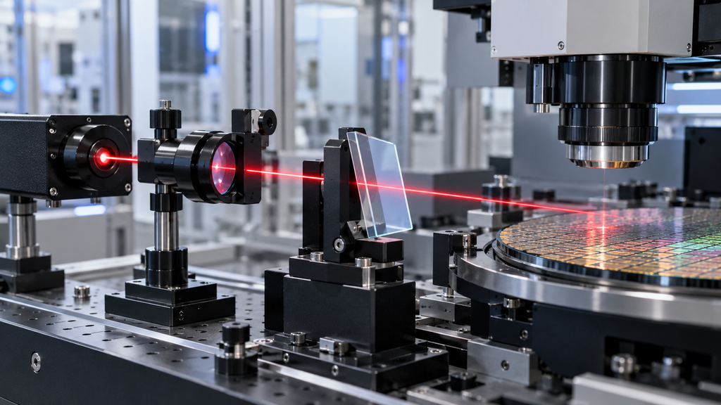
Laser-based metrology and optical inspection systems are increasingly sensitive to effects that may appear insignificant in a conventional optical assembly.
A small unwanted reflection can interfere with a detector.
Two parallel optical surfaces can form a weak etalon.
A slight angular error can shift a laser spot at the measurement plane.
A coating optimized for the wrong wavelength or angle of incidence can increase reflection instead of reducing it.
For this reason, optical windows used in semiconductor metrology should not always be treated as simple transparent protective plates.
In some systems, a wedge sapphire window provides a better solution.
Instead of manufacturing the two optical surfaces perfectly parallel, one surface is intentionally tilted relative to the other by a controlled wedge angle.
This small geometric difference can help separate unwanted back reflections from the primary transmitted beam.
For semiconductor inspection, laser metrology, alignment and process-monitoring equipment, important specifications therefore include:
- Wedge angle
- Wedge orientation
- Beam deviation
- Ghost reflection separation
- Surface flatness
- Transmitted wavefront error
- Surface quality
- Crystal orientation
- AR coating
- Angle of incidence
- Clear aperture
- Edge geometry
This article explains how these parameters interact and what engineers should specify when designing a custom wedge sapphire window.
1. What Is a Wedge Sapphire Window?
A conventional optical window normally has two nominally parallel polished surfaces.
Conceptually:
Surface 1
│
│ Sapphire
│
Surface 2
For a wedge window, the two surfaces are intentionally non-parallel.
The geometry becomes:
Surface 1
╲
╲ Sapphire
╲
Surface 2
The small angle between the two surfaces is the wedge angle.
It may be specified in:
- Degrees
- Arcminutes
- Arcseconds
- Milliradians
depending on the magnitude and precision required.
The wedge may be visually almost impossible to detect, but optically it can have an important effect.
2. Why Use a Wedge Instead of a Parallel Window?
Every uncoated optical interface reflects some portion of incident light.
With a parallel window, a laser can experience reflection at both:
- Front surface
- Rear surface
Some of the rear-surface reflection can travel back along or very close to the original optical path.
This may create:
- Ghost spots
- Detector interference
- Feedback into a laser source
- Etalon effects
- Intensity modulation
- Measurement instability
A wedge changes the direction of the secondary reflected beam.
Instead of overlapping the primary path, the unwanted reflection can be redirected away from the detector or laser source.
This is especially valuable in precision systems where even relatively weak reflections can influence measurement accuracy.
3. Why This Matters in Semiconductor Laser Metrology
Semiconductor metrology can use optical techniques for measurements such as:
- Wafer alignment
- Surface inspection
- Film measurement
- Height measurement
- Overlay measurement
- Focus control
- Position measurement
- Defect detection
- Interferometric measurement
- Laser displacement measurement
- Optical encoder systems
These systems may work with very small signals or very small dimensional changes.
A secondary reflection that would be irrelevant in ordinary viewing optics can become significant when measuring:
- Nanometer-scale displacement
- Small intensity variation
- Phase
- Interference
- Surface height
- Edge position
Optical windows placed between the sensor and target must therefore preserve the intended optical path while preventing parasitic reflections from reaching critical areas.
4. Ghost Reflections From a Parallel Window
Consider a laser entering a conventional plane-parallel window.
At the first surface:
- Most of the light is transmitted
- A small portion is reflected
At the second surface:
- Most transmitted light continues forward
- Another small portion is reflected
That second reflection travels backward through the window.
Additional multiple reflections can also occur between the two surfaces.
The result can include several weak optical paths.
In a broadband imaging system, these may simply produce faint ghost images.
In a coherent laser system, they can become more problematic because the reflected waves can interfere.
5. Etalon Effects
Two parallel polished optical surfaces can behave as a weak Fabry–Pérot etalon.
Light reflected repeatedly between the surfaces can interfere constructively or destructively depending on:
- Wavelength
- Refractive index
- Window thickness
- Angle of incidence
- Temperature
This can produce wavelength-dependent or angle-dependent transmission variation.
For a metrology system, unwanted etalon behavior can appear as:
- Intensity drift
- Periodic measurement error
- Fringes
- Signal instability
Using a wedge prevents the internal reflections from remaining perfectly collinear.
This significantly reduces the tendency of the two surfaces to behave as a parallel etalon.
6. How the Wedge Separates Reflections
Imagine a laser entering the first surface close to normal incidence.
The transmitted beam reaches the second surface.
Because that surface is tilted slightly, its reflected beam returns at a different angle.
As the beam travels farther from the window, the physical separation between:
primary beam
and
ghost beam
increases.
This allows an optical system designer to:
- Block the ghost
- Move it outside the detector
- Prevent it from returning to the source
- Reduce coherent interference
The wedge therefore converts an overlapping reflection problem into an angular separation problem.
7. Wedge Angle Is a Functional Optical Specification
The wedge angle should not be selected arbitrarily.
If the wedge is too small:
- Ghost separation may be insufficient
If the wedge is unnecessarily large:
- Main-beam deviation increases
- Mounting becomes more difficult
- Thickness variation increases
- Optical alignment may become more complicated
Therefore, the correct wedge should be selected according to the complete optical system.
Important variables include:
- Laser wavelength
- Sapphire refractive index
- Beam diameter
- Distance to detector
- Detector active area
- Allowed beam displacement
- Required ghost separation
8. Common Wedge Units
Optical drawings may express wedge using several units.
Degrees
Example:
0.5°
Arcminutes
One degree contains 60 arcminutes.
Example:
5 arcmin
Arcseconds
One arcminute contains 60 arcseconds.
Used for much smaller angular specifications.
Milliradians
Frequently used in engineering systems.
For reference:
1 mrad ≈ 0.0573°
The unit should always be clearly stated.
A specification such as:
Wedge: 5
is incomplete unless the unit is defined.
9. Small Wedge Angles Can Still Produce Significant Beam Separation
For a small optical wedge near normal incidence, a useful first-order approximation for prism-like deviation is:
Beam deviation ≈ (n − 1) × wedge angle
where:
nis the refractive index- wedge angle is expressed in radians
This is only an approximation.
Sapphire is an anisotropic crystal, and its refractive index also changes with wavelength.
For final high-precision designs, engineers should use:
- Exact Snell’s-law calculations
- Crystal-orientation data
- Actual wavelength
- Polarization
- Optical ray tracing
However, the approximation helps explain an important principle:
A very small physical wedge can create a measurable angular beam deviation.
10. Sapphire Has a Relatively High Refractive Index
Sapphire has a higher refractive index than common optical materials such as fused silica.
The exact value depends on:
- Wavelength
- Crystal axis
- Polarization
Because the refractive index is relatively high, two consequences become important:
- An uncoated sapphire surface produces meaningful Fresnel reflection.
- A given wedge angle can create noticeable beam deviation.
Therefore, wedge geometry and AR coating should normally be considered together.
11. Wedge Angle and Beam Deviation Are Not the Same Specification
This distinction is important.
Wedge angle
describes the geometry between the two window surfaces.
Beam deviation
describes what happens to the transmitted optical beam.
Beam deviation depends on more than the wedge angle.
It also depends on:
- Refractive index
- Wavelength
- Angle of incidence
- Crystal orientation
- Polarization
Therefore, a customer may specify either:
Wedge angle = X
or
Maximum transmitted beam deviation = Y
or both.
For a metrology system, the second specification may be more directly connected to actual equipment performance.
12. Why Beam Deviation Matters in Metrology
Suppose a sapphire wedge window sits relatively far from a detector.
A small angular deviation can become a significant lateral displacement.
Conceptually:
Angular error × optical path length → spot displacement
If the beam travels a long distance after the window, even a small angular change may move the spot enough to affect:
- Detector position
- Calibration
- Alignment
- Measurement repeatability
The acceptable wedge should therefore be evaluated at the system level.
Do not judge it only by how small the angle looks on the mechanical drawing.
13. Sometimes Beam Deviation Is Intentional
Not every beam shift is undesirable.
In some optical systems, the wedge is intentionally designed to steer the unwanted reflection in a specific direction.
For example:
Main transmitted beam
→ detector
while:
rear-surface reflection
→ beam dump
The wedge direction therefore matters.
This is why wedge orientation may need to be referenced to:
- A flat on the window
- A notch
- A mechanical datum
- A mounting feature
The optical designer can then control where the ghost reflection goes.
14. Wedge Direction Should Be Defined
A circular wedge window has a high side and a low side.
If the mounting system can rotate the window freely, the ghost reflection direction will also rotate.
For some applications this does not matter.
For semiconductor laser metrology, it may matter greatly.
A drawing can therefore define:
- High-side orientation
- Low-side orientation
- Reference flat
- Crystal axis
- Coating side
For example:
High side aligned with OD flat
This gives the equipment manufacturer a repeatable installation reference.
15. Ghost Reflection Separation at the Detector
The useful ghost separation depends on:
- Angular separation
- Distance
- Beam diameter
If the ghost beam remains inside the same detector aperture, the wedge may not solve the problem.
If the ghost is shifted far enough away, it can be:
- Blocked
- Absorbed
- Ignored by the sensor
Therefore, engineers should calculate not only angular deviation but also the expected ghost position at the relevant optical plane.
16. Detector Size Matters
A wedge designed for one detector may be unsuitable for another.
For example:
Large-Area Photodiode
A weak ghost may still fall onto the active surface.
Small-Area Detector
The same angular separation may move the ghost completely outside the active area.
Camera Sensor
A ghost may create a secondary image or local illumination artifact.
Interferometer
Even a weak reflected beam may alter phase measurement.
Therefore, acceptable ghost separation is application-specific.
17. AR Coating and Wedge Solve Different Problems
It is tempting to ask:
If the window is AR coated, why do we still need a wedge?
Because these technologies address different parts of the problem.
AR Coating
Reduces the amount of reflected optical power.
Wedge
Changes the direction of the reflected optical power.
Using them together can be more effective than relying on either one alone.
A small residual reflection may still matter in a sensitive laser system.
If that residual reflection is also redirected away from the critical path, its impact can be reduced further.
18. Uncoated Sapphire Can Produce Significant Surface Reflection
Because sapphire has a relatively high refractive index, Fresnel reflection at an air-sapphire interface is higher than for some lower-index optical materials.
Therefore, a laser passing through an uncoated sapphire window can experience meaningful reflection at each surface.
This is why AR coatings are often valuable in:
- Laser systems
- Metrology
- Imaging
- Inspection
- Optical monitoring
especially when maximum transmitted power or low back reflection is required.
19. AR Coating Must Match the Wavelength
There is no universal AR coating that performs equally well across every wavelength.
A coating is normally designed for a target spectral range.
Examples may include:
- 355 nm
- 405 nm
- 532 nm
- 633 nm
- 808 nm
- 1064 nm
- 1550 nm
or broader ranges such as:
- VIS
- VIS-NIR
- NIR
- SWIR
For a semiconductor laser metrology system, the actual laser wavelength should be provided during coating design.
20. Angle of Incidence Also Matters
An AR coating designed for normal incidence may not perform identically at:
- 15°
- 30°
- 45°
The optical thickness condition changes with incidence angle.
Polarization dependence also becomes more important at larger angles.
Therefore, the coating RFQ should specify:
AOI = angle of incidence
and, when important:
polarization = S / P / random
A coating described only as:
AR coating for 1064 nm
may be insufficient for a precision metrology application.
21. Single-Wavelength vs Broadband AR Coating
A narrowband laser metrology system may benefit from an AR coating optimized around one wavelength.
Advantages can include:
- Lower residual reflectance at target wavelength
- Better laser throughput
- Reduced back reflection
A multi-wavelength inspection system may instead require broadband AR performance.
The coating design should therefore follow the instrument architecture.
22. Coating Both Surfaces vs One Surface
Depending on the system, engineers may specify:
- AR coating on Surface 1
- AR coating on Surface 2
- AR coating on both surfaces
For maximum transmission through a protective window, both surfaces are commonly considered.
However, there are applications where one surface performs another optical function.
The drawing should clearly identify:
S1
and
S2
rather than simply stating:
AR coated
23. Coating Uniformity Across a Wedge
Because a wedge has non-parallel surfaces, coating fixtures and deposition geometry require careful control.
For high-performance coatings, manufacturers must consider:
- Surface angle
- Clear aperture
- Part orientation
- Coating uniformity
A coating that performs correctly at the center should also satisfy the required performance across the usable optical aperture.
24. Laser Damage Threshold
If the window is used with a high-power laser, coating selection must consider more than reflectance.
The coating must also withstand the optical intensity.
Relevant information can include:
- CW or pulsed operation
- Average power
- Pulse energy
- Pulse width
- Repetition rate
- Beam diameter
- Beam profile
- Wavelength
A coating suitable for a low-power alignment laser may not be suitable for a high-energy pulsed metrology source.
25. Surface Quality Is Critical for Laser Applications
Optical surface defects can scatter light.
Typical surface quality specifications use scratch-dig terminology such as:
- 60-40
- 40-20
- 20-10
- 10-5
The required grade depends on:
- Laser power
- Beam diameter
- Detector sensitivity
- Scattered-light budget
- Application criticality
A semiconductor viewing window does not necessarily require the same surface quality as a precision laser interferometer.
Again, the specification should follow function.
26. Why Scatter Can Affect Metrology
Even if a scratch does not visibly block the beam, it can scatter optical energy into unwanted directions.
In sensitive systems this may increase:
- Background signal
- Stray light
- Detector noise
- Calibration uncertainty
Therefore, surface quality should be considered together with:
- AR coating
- wedge
- internal baffling
when designing the overall stray-light strategy.
27. Surface Flatness
Surface flatness describes how closely an individual polished surface follows an ideal plane.
Common specifications may include:
- λ
- λ/2
- λ/4
- λ/10
at a specified reference wavelength and clear aperture.
A precision laser system may need tighter flatness than a simple machine-vision viewport.
But flatness should not be confused with transmitted wavefront distortion.
28. Transmitted Wavefront Distortion
A window can have two individually good surfaces and still change the transmitted wavefront because of:
- Thickness variation
- Material inhomogeneity
- Surface geometry
- Crystal effects
Transmitted wavefront error is therefore often a more system-relevant parameter.
For semiconductor metrology, where focus and phase may matter, engineers should consider specifying transmitted wavefront performance where appropriate.
29. Wedge and Parallelism Are Opposite Design Intentions
For a normal precision optical window, drawings often attempt to make the surfaces highly parallel.
For a wedge window, non-parallelism is intentional.
Therefore, a specification such as:
Parallelism ≤ 10 arcsec
would conflict with a design requiring:
Wedge = 5 arcmin
The drawing should clearly distinguish:
- Intentional wedge
- Wedge tolerance
- Surface flatness
Do not use a generic flat-window drawing and simply add the word “wedged.”
30. Wedge Tolerance Matters
The nominal wedge alone is not sufficient.
For example:
Wedge: 5 arcmin ± 1 arcmin
is more useful than:
Wedge: approximately 5 arcmin
The tolerance determines the possible variation in:
- Beam deviation
- Ghost location
- Edge thickness
If the system relies on the ghost beam landing in a specific beam dump, wedge tolerance may be important.
31. Thickness Variation Across the Window
A wedge naturally produces different thicknesses on opposite sides.
For a circular window:
High side = thicker
Low side = thinner
The mechanical design must therefore accommodate:
- Maximum thickness
- Minimum thickness
- Mounting contact
- Retaining ring position
A mounting system designed around a parallel plate may clamp a wedge unevenly if this variation is ignored.
32. Minimum Edge Thickness
The thin side of a wedge deserves special attention.
If the wedge angle is too large relative to:
- Diameter
- Center thickness
the minimum edge thickness can become too small.
This may reduce:
- Mechanical strength
- Edge durability
- Coating margin
Therefore, an RFQ should specify either:
- Center thickness
or
- High-side/low-side thickness
together with the wedge.
33. Mechanical Mounting Should Not Flatten the Wedge
A wedge window should not be forced into a mounting geometry that assumes two perfectly parallel faces.
Excessive clamping can introduce:
- Stress
- Distortion
- Birefringence effects
- Fracture risk
The mount should support the sapphire without creating large localized loads.
Common strategies can include:
- Compliant retainers
- Controlled preload
- Appropriate gasket materials
- Edge support
Actual mounting should be engineered according to temperature and vacuum requirements.
34. Sapphire Is Mechanically Strong but Still Brittle
Sapphire is extremely hard and resistant to scratching compared with conventional optical glass.
This makes it attractive for harsh equipment environments.
However, hardness does not mean the material is impossible to break.
Sapphire remains a brittle single crystal.
Edge chips and concentrated mechanical loads can still initiate fracture.
Protective bevels are therefore commonly used around optical windows.
35. Edge Bevel Requirements
A wedge sapphire window may include:
- Protective bevel
- Chamfer
- Radius
- Ground edge
The edge treatment helps reduce chipping during:
- Manufacturing
- Coating
- Assembly
- Maintenance
For small optical windows, the bevel should remain outside the clear aperture.
A drawing should therefore define:
OD + bevel + clear aperture
together.
36. Clear Aperture
The clear aperture is the region over which the optical specification must be maintained.
It may be smaller than the physical diameter.
For example:
OD: 50 mm
Clear aperture: central 45 mm
Optical specifications such as:
- Surface quality
- Flatness
- Coating performance
may apply only inside this region.
This distinction can reduce unnecessary fabrication cost at the edge.
37. Crystal Orientation Matters for Sapphire
Sapphire is a single-crystal material.
Unlike amorphous fused silica, its optical behavior depends on crystallographic orientation.
Sapphire is birefringent.
This means refractive index can vary according to:
- Crystal axis
- Beam direction
- Polarization
For precision laser applications, the crystal orientation should therefore be specified.
38. C-Axis Sapphire for Laser Windows
C-axis-oriented sapphire is frequently selected for optical windows.
When optical propagation is appropriately aligned relative to the C-axis, birefringence effects can be minimized.
Commercial laser-grade sapphire windows are commonly offered using controlled C-axis orientation for this reason.
For a precision wedge design, however, engineers should consider the actual:
- Wedge orientation
- Beam angle
- Crystal axis
- Polarization
rather than assuming crystallographic effects disappear under every oblique configuration.
39. Why Crystal Orientation Becomes More Important With a Wedge
A plane-parallel C-axis window used at near-normal incidence can have a relatively straightforward optical path.
A wedge changes the local relationship between:
- Surface normal
- Beam direction
- Crystal axis
Depending on wedge magnitude and system geometry, this can introduce additional polarization considerations.
For demanding interferometric or polarization-sensitive systems, optical modeling should therefore include sapphire anisotropy.
40. Wavelength Changes Refractive Index
The refractive index of sapphire is dispersive.
That means:
n at 355 nm ≠ n at 532 nm ≠ n at 1064 nm
Therefore, the beam deviation produced by the same physical wedge changes somewhat with wavelength.
This matters for a system using multiple wavelengths.
A wedge that produces ideal separation at one wavelength may produce a slightly different beam position at another.
Multi-wavelength systems should therefore be evaluated across the full operating range.
41. Broadband Metrology Systems
Some semiconductor inspection systems combine:
- Visible illumination
- Near-IR
- Laser alignment
- Spectroscopic measurement
If several wavelengths must pass through the same sapphire window, engineers should evaluate:
- Chromatic beam deviation
- AR coating bandwidth
- Detector alignment
- Sapphire transmission
- Birefringence
A broadband wedge window is a more complex optical component than a single-wavelength protective window.
42. Temperature Can Affect the Optical Path
Sapphire is often selected because it performs well in high-temperature environments.
However, precision metrology may still need to consider temperature-dependent changes in:
- Refractive index
- Physical dimensions
- Coating behavior
- Mounting stress
For a window separating a room-temperature optical system from a hot process chamber, temperature gradients can also develop across the material.
These effects should be considered when the required measurement accuracy is extremely high.
43. Why Sapphire Is Attractive Near Semiconductor Process Chambers
Sapphire provides a useful combination of:
- High hardness
- Thermal stability
- Chemical resistance
- Optical transmission
- Mechanical durability
This makes it useful when an optical measurement system needs a window between the instrument and a demanding process environment.
Potential equipment locations include:
- Plasma chambers
- Vacuum chambers
- Thermal equipment
- Process monitoring ports
- Laser alignment systems
- Optical inspection modules
The wedge can then be added when optical back reflection must also be controlled.
44. Sapphire vs Fused Silica Wedge Windows
Both materials can be used for wedge windows, but they serve different needs.
Fused Silica
Advantages may include:
- Excellent UV performance
- Low optical absorption
- Low thermal expansion
- No crystal birefringence
Sapphire
Advantages may include:
- Much greater hardness
- High mechanical durability
- Strong chemical resistance
- High-temperature capability
- Broad optical transmission
For a protected laboratory laser path, fused silica may be entirely suitable.
For a semiconductor equipment viewport exposed to:
- Particles
- aggressive environments
- repeated cleaning
- elevated temperature
sapphire may provide better mechanical durability.
Material choice should follow the actual operating environment.
45. Wedge Sapphire Window vs Tilted Parallel Window
Another design question is:
Why not simply tilt a normal parallel sapphire window?
Tilting a parallel window can redirect front- and rear-surface reflections relative to the system.
This may work in some optical layouts.
However, tilting the entire window can also produce:
- Beam walk-off
- Mechanical packaging difficulties
- Increased astigmatic effects in some systems
- Larger required aperture
A built-in wedge allows the window orientation and ghost separation to be engineered more specifically.
The best approach depends on the optical layout.
46. Wedge Window vs Beam Sampler
A wedge window is not necessarily a beam sampler.
A beam sampler intentionally directs a known fraction of optical power to another path for monitoring.
A wedge window primarily uses geometry to separate unwanted reflections.
However, the same underlying optical principles can sometimes be used deliberately to create a monitoring beam.
The distinction should be made clear in the optical design.
47. Laser Metrology Applications
Custom wedge sapphire windows may be relevant to equipment including:
Wafer Surface Metrology
Protecting optical sensors while suppressing unwanted reflections.
Laser Displacement Measurement
Reducing ghost signals that could influence distance measurements.
Interferometric Systems
Reducing parasitic cavity effects from parallel optical interfaces.
Alignment Systems
Controlling secondary reflections near alignment cameras or photodiodes.
Process Monitoring
Protecting optical instrumentation from process conditions.
Wafer Inspection
Providing a durable optical barrier in systems requiring repeated high-throughput operation.
48. Example Optical Path
A simplified system may look like:
Laser Source
↓
Beam Conditioning Optics
↓
Wedge Sapphire Window
↓
Process / Wafer
↓
Measurement Signal
↓
Detector
The window should transmit the primary beam with minimal distortion.
At the same time:
front-surface reflection
and
rear-surface reflection
should be controlled so that they do not re-enter:
- Laser source
- Detector
- Measurement path
This is the central reason for engineering the wedge.
49. Important RFQ Parameters
A useful RFQ for a custom wedge sapphire window should include:
| Parameter | What to Specify |
|---|---|
| Material | Optical-grade sapphire |
| Crystal orientation | C-axis or required orientation |
| Diameter / size | mm |
| Center thickness | mm |
| Wedge angle | deg / arcmin / mrad |
| Wedge tolerance | Required range |
| Wedge direction | Reference to flat/notch if needed |
| Surface flatness | λ value and reference wavelength |
| Transmitted wavefront | If required |
| Surface quality | Scratch-dig |
| Surface roughness | If required |
| Clear aperture | % or dimensional value |
| Coating | AR / BBAR / uncoated |
| Wavelength | nm |
| AOI | Degrees |
| Polarization | S/P/random if important |
| Reflectance | Maximum target |
| Laser power | CW or pulse conditions |
| Edge | Ground / polished / bevel |
| Environment | Vacuum / plasma / temperature |
| Quantity | Prototype / production |
50. Example Wedge Sapphire Window RFQ
A technically useful inquiry could look like:
Product: Wedge Sapphire Optical Window
Application: Semiconductor Laser Metrology
Material: Optical-Grade Sapphire
Crystal Orientation: C-Axis
Diameter: Ø50.00 mm
Center Thickness: 3.00 mm
Wedge Angle: 5 arcmin ±1 arcmin
Wedge Direction: High side referenced to OD flat
Surface Quality: 20-10 scratch-dig
Surface Flatness: According to drawing
Transmitted Wavefront: Customer specified
Clear Aperture: ≥90%
Coating: AR both sides
Laser Wavelength: 1064 nm
AOI: Near normal incidence
Laser Type: Customer specified
Edge: Fine ground with protective bevel
Quantity: 5 pcs qualification, followed by production
This contains enough information for meaningful optical and manufacturing evaluation.
51. Wedge Angles Should Not Be Copied From Another Design
A common mistake is to see:
30 arcmin wedge
on a standard catalog optic and use the same value for a different system.
That number may not be appropriate.
The required wedge should be calculated from:
- Desired ghost separation
- Available optical distance
- Beam diameter
- Sapphire index
- Detector dimensions
- Allowed main-beam deviation
In some systems only a few arcminutes may be required.
Others may use much larger wedge angles.
The correct value is system-specific.
52. Prototype Optical Testing
For a new metrology system, prototype windows should ideally be evaluated inside the actual optical setup.
Tests can include:
- Main-beam position
- Ghost-beam location
- Total transmission
- Back reflection
- Wavefront distortion
- Detector background
- Temperature behavior
This can verify whether the calculated wedge works as expected.
53. Measure the Ghost, Not Just the Window
A dimensional inspection can confirm:
wedge angle = specification
but that does not automatically prove:
metrology system performance = acceptable
The final qualification should evaluate the optical effect.
For example:
Where does the ghost reflection actually land?
This is ultimately more important than the wedge-angle number itself.
54. Coating Qualification
For a critical laser application, coating qualification may include:
- Spectral reflectance
- Transmission
- Coating uniformity
- Environmental durability
- Adhesion
- Laser damage testing where applicable
If the sapphire window operates inside semiconductor equipment, coating compatibility with:
- Temperature
- cleaning
- vacuum
- process atmosphere
should also be considered.
55. Cleaning Wedge Sapphire Windows
Sapphire is highly scratch resistant, but precision optical surfaces should still be handled carefully.
Cleaning procedures should avoid:
- Particle dragging
- Contaminated wipes
- Dirty fixtures
- Coating damage
For semiconductor equipment, contamination requirements may also demand controlled cleaning and packaging.
The window should therefore be considered both:
an optical component
and
a clean-process component.
56. Orientation Marking
For custom wedge windows, physical orientation marking can simplify assembly.
Possible methods include:
- OD flat
- Small notch
- Drawing-defined reference mark
- Package orientation label
The marker can indicate:
- High side
- Crystal axis
- Coating side
This helps prevent installation errors during equipment assembly or maintenance.
57. Questions to Ask a Sapphire Window Manufacturer
Before placing an order, engineers should ask:
- What wedge-angle tolerance can be maintained?
- How is wedge angle measured?
- Can wedge direction be referenced to an OD flat?
- What C-axis orientation tolerance is available?
- How is transmitted wavefront measured?
- What surface quality can be achieved?
- What clear aperture is guaranteed?
- Can both surfaces receive AR coating?
- Can the AR coating be optimized for the actual AOI?
- What laser damage data are available?
- Can coating reflectance data be supplied?
- How is sapphire birefringence considered?
- Can custom rectangular or irregular wedge windows be fabricated?
- What minimum edge thickness is recommended?
- Can the part be supplied with inspection data?
- Is prototype optical qualification available?
These questions help distinguish a precision optical component from a simple sapphire plate.
58. Design Principle: Start With the Optical Problem
The best way to specify a wedge sapphire window is not to begin with:
“We need a 5 arcmin wedge.”
Start with the actual problem:
“The rear-surface ghost must miss a 2 mm detector located 300 mm away.”
or:
“Back reflection into the laser source must be minimized.”
or:
“Etalon fringes from a parallel protective window are affecting the measurement.”
Once the optical requirement is defined, engineers can determine:
- Wedge angle
- Orientation
- AR coating
- surface quality
- transmitted wavefront
- thickness
This produces a better optical design.
Conclusion
A wedge sapphire window used in semiconductor laser metrology is much more than a sapphire plate with two slightly non-parallel surfaces.
Its performance depends on the interaction of:
wedge angle + refractive index + wavelength + beam deviation + ghost separation + AR coating + crystal orientation + surface quality
The wedge redirects unwanted reflections.
The AR coating reduces their intensity.
Surface quality controls scattering.
Flatness and transmitted wavefront influence beam quality.
Crystal orientation becomes important because sapphire is birefringent.
And mechanical mounting must preserve the optical geometry without placing excessive stress on the window.
For semiconductor metrology engineers, the key design question should therefore not be:
“What wedge angle is standard?”
but:
“How far must the unwanted reflection be moved, and how much deviation can the measurement beam tolerate?”
From there, the window can be engineered around the real optical system.
A complete custom RFQ should define:
material, crystal orientation, size, thickness, wedge angle, wedge direction, surface quality, flatness, transmitted wavefront, clear aperture, wavelength, angle of incidence, polarization and AR coating requirements.
When these parameters are controlled together, a wedge sapphire window can provide a durable and effective optical interface for precision semiconductor inspection, laser metrology and process-monitoring equipment.