
A sapphire vacuum viewport is more than an optical window mounted on a vacuum chamber. It is simultaneously an optical component, vacuum boundary, mechanical pressure barrier and thermal interface.
In semiconductor process equipment, coating systems, plasma chambers, analytical instruments, research vacuum systems and laser processing equipment, an improperly designed viewport can cause slow pump-down, helium leakage, optical distortion, coating failure or even window fracture.
Single-crystal sapphire is attractive for vacuum optical applications because of its high hardness, heat resistance, chemical resistance and broad optical transparency. Sapphire is also used commercially for vacuum equipment and reaction-furnace windows.
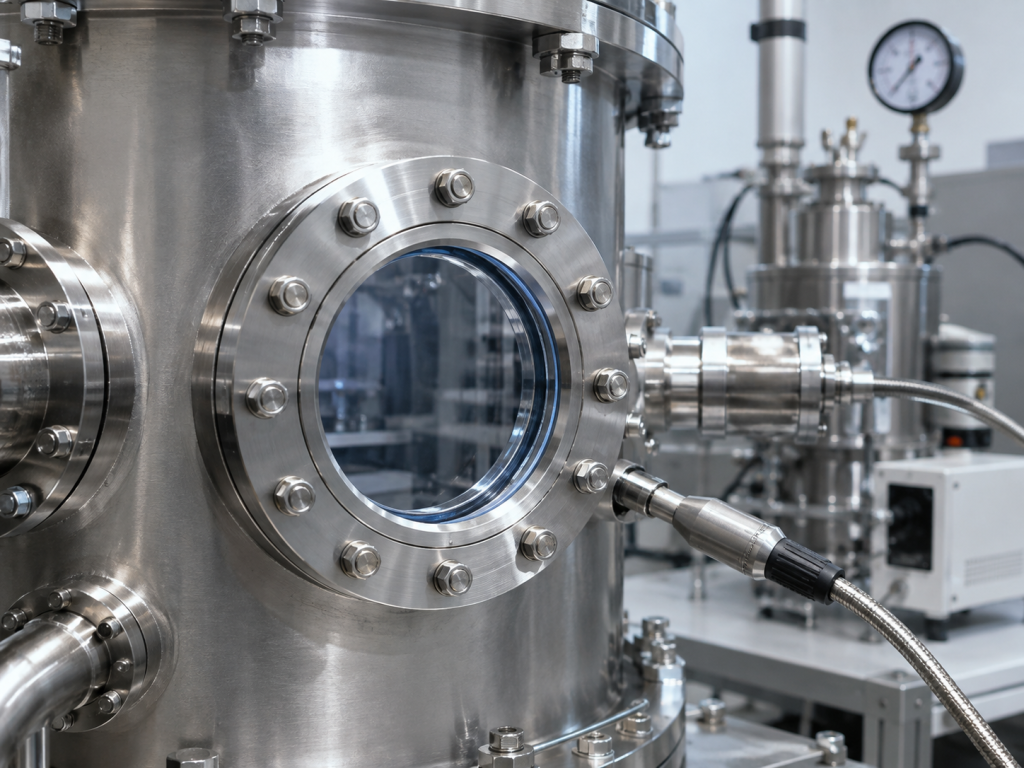
However, selecting sapphire alone does not guarantee a reliable viewport. Engineers must consider the complete assembly:
- Sapphire diameter and thickness
- Clear aperture
- Crystal orientation
- Optical surface quality
- Flange standard
- Sealing technology
- Differential pressure
- Bakeout temperature
- Thermal cycling
- Helium leak-rate requirement
- AR coating
- Mounting stress
This guide explains the major design decisions involved in specifying a custom sapphire vacuum viewport.
1. What Is a Sapphire Vacuum Viewport?
A vacuum viewport creates an optical path through the wall of a sealed chamber while maintaining the required vacuum level.
Typical applications include:
- Plasma observation
- Laser beam delivery
- Optical emission spectroscopy
- Pyrometry
- Machine vision
- UV optical monitoring
- IR sensing
- Semiconductor chamber inspection
- Vacuum deposition monitoring
- Scientific instruments
- High-temperature vacuum equipment
Commercial sapphire viewports are available as hermetically sealed assemblies in both CF and KF flange configurations, illustrating the material’s suitability for vacuum optical interfaces.
Depending on the application, the viewport may only need to provide visual access, or it may be part of a precision optical system where transmitted wavefront, surface flatness, wedge and coating performance are critical.
2. Start With the Vacuum Level
Before choosing the sapphire window itself, determine the required operating pressure.
The required vacuum level strongly influences the flange and sealing design.
A system operating at moderate vacuum may tolerate elastomer seals, while demanding ultra-high-vacuum systems usually favor all-metal sealing arrangements. Elastomer O-rings introduce permeation and outgassing that can become limiting factors as the target base pressure becomes more demanding.
A useful RFQ should therefore specify:
Operating vacuum:
For example, 10⁻⁶ mbar, 10⁻⁸ mbar or UHV
External pressure:
Normally atmospheric, or another specified pressure
Positive internal pressure:
If applicable
Process gas:
Air, nitrogen, argon, oxygen, hydrogen, corrosive gases, plasma gases, etc.
Operating temperature:
Normal process temperature at the viewport
Bakeout temperature:
Maximum temperature during vacuum conditioning
These parameters should be confirmed before the flange or window thickness is finalized.
3. CF vs KF Flanges for Sapphire Viewports
CF Flanges
CF, or ConFlat-style, flanges are widely used for high-vacuum and ultra-high-vacuum systems.
They typically use a metal gasket compressed between mating knife edges. All-metal CF connections are preferred for demanding UHV systems because they eliminate elastomer permeability and can support high-temperature bakeout.
Industry guidance for CF systems specifically recommends fully annealed copper gaskets when installing fragile components such as viewports because they can help reduce induced mechanical strain.
CF sapphire viewports are therefore a strong choice when the application requires:
- Ultra-high vacuum
- High-temperature bakeout
- Very low gas load
- Long-term vacuum stability
- Semiconductor vacuum chambers
- Surface-science equipment
- Beamline equipment
- High-vacuum research systems
Important Design Point
A strong sapphire window can still fail if excessive flange distortion or installation stress is transferred into the optical element.
The viewport should therefore be treated as a complete mechanical assembly, not simply as a sapphire disk attached to a metal flange.
KF Flanges
KF, also called NW or QF in some systems, uses a centering ring, elastomer O-ring and external clamp.
KF systems offer:
- Fast installation
- Easy removal
- Lower installation complexity
- Convenient maintenance
They are commonly suitable for high-vacuum systems where frequent disassembly is required.
However, KF elastomer seals have higher gas permeability and generally lower temperature capability than all-metal CF seals, so they are less attractive for demanding long-term UHV service.
Simple Selection Rule
Choose CF when UHV performance, bakeout temperature and minimum gas permeation are priorities.
Choose KF when convenience, frequent removal and moderate vacuum requirements are more important.
The actual decision should still be based on the complete vacuum-system specification.
4. Sapphire-to-Metal Sealing Is Often the Critical Area
The sapphire itself may have excellent mechanical and thermal properties, but the interface between sapphire and the metal housing is often where engineering becomes more difficult.
Sapphire and metals have different thermal expansion behavior.
During:
- Brazing
- Bakeout
- Cooling
- Thermal cycling
- Chamber heating
the metal structure and sapphire optic may expand or contract by different amounts.
If this differential movement is constrained too strongly, tensile stress can develop near the sapphire edge.
Potential consequences include:
- Edge cracking
- Seal failure
- Optical distortion
- Birefringence caused by mechanical stress
- Loss of hermeticity
- Complete viewport failure
The seal design should therefore accommodate the thermal and mechanical behavior of the entire assembly.
5. Common Sapphire Viewport Sealing Approaches
The exact construction depends on vacuum level, temperature and production method, but several sealing concepts are commonly considered.
Hermetic Metal-to-Sapphire Assembly
For demanding vacuum systems, the sapphire can be integrated into a purpose-designed metal assembly using a hermetic joining process.
The key design objective is maintaining vacuum integrity without placing excessive residual stress on the sapphire.
Important variables include:
- Sapphire geometry
- Metal alloy
- Intermediate materials
- Joint geometry
- Joining temperature
- Cooling rate
- Thermal expansion mismatch
- Required leak rate
Elastomer O-Ring Seal
For less demanding vacuum systems, a removable sapphire plate may be sealed using an O-ring.
Advantages include:
- Easy replacement
- Simple machining
- Lower assembly cost
However, elastomer permeability, outgassing and temperature limits must be considered. Pfeiffer notes that elastomer seals can become a major factor determining achievable final pressure when other sources of gas have been minimized.
For high-temperature bakeout or demanding UHV operation, an all-metal or hermetic design is generally more appropriate.
6. Clear Aperture Is Not the Same as Sapphire Diameter
One common RFQ mistake is specifying only the outside diameter of the sapphire.
For a vacuum viewport, engineers should distinguish between:
Outer Diameter (OD)
Total sapphire diameter.
Clear Aperture (CA)
Usable optical opening.
Supported Diameter
Area mechanically captured by the mounting structure.
These dimensions directly affect stress distribution.
For example, two windows may both use a Ø50 mm sapphire disk, but:
- Window A may have a Ø40 mm clear aperture.
- Window B may have a Ø46 mm clear aperture.
Window B leaves much less supported edge area and may experience significantly different mechanical loading.
For this reason, viewport thickness should never be selected from outside diameter alone.
7. Sapphire Thickness and Pressure Differential
A vacuum viewport normally experiences approximately one atmosphere of differential pressure when the chamber is evacuated and the external side remains at atmospheric pressure.
The resulting stress depends on several variables:
- Unsupported aperture diameter
- Sapphire thickness
- Edge support
- Window geometry
- Material strength
- Surface condition
- Edge condition
- Mounting stress
- Safety factor
Scratches and edge damage are particularly important because viewports are pressure boundaries. Vacuum-component manufacturers specifically warn that scratching a viewport can weaken it and increase failure risk.
Therefore, thickness should be determined from the real mechanical design rather than selected from a generic diameter-to-thickness table.
For custom engineering projects, buyers should provide:
Pressure differential: ___
Clear aperture: ___ mm
Sapphire thickness: ___ mm or supplier recommendation
Required safety factor: ___
Temperature range: ___ °C
8. Bakeout Temperature Must Be Specified for the Whole Assembly
Vacuum systems are often heated during bakeout to accelerate desorption of water vapor and other adsorbed gases.
But the maximum temperature of a sapphire viewport is not simply the maximum temperature that bulk sapphire can withstand.
The practical limit may be controlled by:
- Hermetic seal
- Braze alloy
- Flange
- AR coating
- O-ring
- Adhesive, if used
- Metal housing
- Temperature gradient
This distinction is extremely important.
A sapphire substrate may tolerate temperatures far above the rating of the assembled viewport.
Therefore, a drawing or RFQ should specify:
Maximum operating temperature: ___ °C
and separately:
Maximum bakeout temperature: ___ °C
9. Avoid Rapid Heating and Cooling
Thermal gradients are particularly dangerous for viewports.
If the metal flange heats much faster than the optical element, differential expansion can create large stresses at the interface.
Kurt J. Lesker’s viewport technical guidance recommends avoiding rapid temperature changes and indicates that a cautious heating rate around 2°C/min can be appropriate for sensitive viewport assemblies.
This should not be interpreted as a universal sapphire specification.
The correct heating and cooling rate must come from the specific viewport design and manufacturer’s qualification data.
As a general engineering principle:
- Heat gradually.
- Cool gradually.
- Avoid localized heaters directly beside the optical joint.
- Minimize temperature gradients across the window.
- Confirm coating temperature limits.
- Confirm seal temperature limits.
10. Bakeout Should Not Be Used to Hide a Leak
Bakeout can reduce water vapor and other desorbed gases, but it cannot repair a physical leak.
For UHV systems, leak detection should normally be completed before final high-temperature conditioning. Pfeiffer recommends helium leak detection after installation to confirm system tightness before bakeout and final pump-down.
If a system fails to reach its expected pressure, engineers should differentiate among:
- Real atmospheric leaks
- Virtual leaks
- Outgassing
- Permeation
- Contamination
- Pump limitations
This distinction prevents unnecessary bakeout cycles and helps locate the actual problem.
11. Helium Leak Testing of Sapphire Vacuum Viewports
Helium mass-spectrometer leak testing is one of the most effective methods for evaluating vacuum assemblies.
In a common vacuum spray test:
- The chamber is evacuated.
- The helium leak detector is connected to the vacuum system.
- Small amounts of helium are applied around possible leak locations.
- The detector monitors whether helium enters the vacuum system.
Typical areas to test around a sapphire viewport include:
- Sapphire-to-metal joint
- Brazed interface
- Weld
- CF gasket
- O-ring
- Flange connection
Pfeiffer describes helium spraying around seals, welds, valves and flanges as a standard approach for locating vacuum leaks.
Helium mass-spectrometer systems can measure leak rates far below those detectable through basic pressure-decay tests.
12. Specify the Required Leak Rate in the RFQ
Do not simply write:
“Must be vacuum tight.”
Different applications interpret vacuum tightness differently.
Instead, specify a measurable acceptance criterion such as:
Maximum allowable helium leak rate:
≤ ___ mbar·L/s
or
≤ ___ Torr·L/s
The required value should be determined by the intended vacuum level, chamber volume, pump performance and process stability.
Also specify whether testing applies to:
- Individual viewport
- Completed flanged assembly
- Finished chamber installation
For high-value UHV components, a leak-test report may also be requested.
13. Optical Requirements Still Matter
Vacuum performance is only half of the specification.
For laser, imaging or spectroscopy applications, the buyer should also define:
- Wavelength range
- Surface quality
- Flatness
- Parallelism
- Wedge
- Surface roughness
- Crystal orientation
- Clear aperture
- AR coating
- Transmitted wavefront requirement
Sapphire provides broad optical transparency and can be AR-coated for specific wavelength ranges to reduce surface reflection.
If the viewport is only used for visual observation, optical tolerances may be relatively relaxed.
If it carries a precision laser beam, however, excessive wedge, surface deformation or mounting stress can affect beam position and wavefront quality.
14. AR Coatings Require Separate Temperature Verification
A sapphire optic and its AR coating should never be assumed to have identical temperature limits.
An AR-coated viewport may be limited by the coating even when the sapphire and metal structure can operate at a higher temperature.
Therefore, the RFQ should clearly state:
Wavelength: 1064 nm
or
AR range: 400–700 nm
along with:
Maximum operating temperature: ___ °C
Maximum bakeout temperature: ___ °C
This allows the coating design to be evaluated together with the vacuum requirements.
15. Typical Failure Modes of Sapphire Vacuum Viewports
Edge Chipping
Often related to machining damage, handling or installation.
Even small edge defects can become stress concentrators.
Excessive Mounting Stress
Uneven clamping or flange distortion can transfer stress into the sapphire.
Thermal Shock
Rapid heating or cooling can produce temperature gradients between the sapphire and metal assembly.
Seal Leakage
Possible sources include braze defects, scratches, contaminated flange surfaces or damaged gaskets.
Coating Degradation
AR coatings may fail if temperature, plasma exposure or chemical conditions exceed their design limits.
Optical Contamination
Vacuum deposition processes can coat the inside surface of the viewport.
For deposition environments, viewport shutters are commonly recommended to protect optical surfaces from process buildup.
16. Sapphire Vacuum Viewport RFQ Checklist
When requesting a custom sapphire vacuum viewport, provide as much of the following information as possible.
Sapphire
- Outside diameter or length × width
- Thickness
- Clear aperture
- Crystal orientation
- Surface quality
- Flatness
- Parallelism
- Surface roughness
- Edge geometry
Optical
- Working wavelength
- AR coating requirement
- Transmission requirement
- Wavefront requirement
- Wedge tolerance
Vacuum
- Operating pressure
- Required base pressure
- Helium leak-rate limit
- Process gas
Mechanical
- CF / KF / ISO / custom flange
- Flange size
- Differential pressure
- Positive pressure, if applicable
- Mounting orientation
Thermal
- Operating temperature
- Bakeout temperature
- Heating/cooling rate
- Number of thermal cycles
Quantity
- Prototype quantity
- Production quantity
- Annual demand
Providing these parameters at the RFQ stage greatly reduces the risk of selecting an optical window that works optically but fails mechanically or in vacuum service.
Conclusion
A reliable sapphire vacuum viewport requires much more than selecting a high-quality sapphire window.
The complete assembly must balance:
optical performance + mechanical strength + flange design + sealing + thermal expansion + bakeout resistance + vacuum integrity.
For moderate vacuum applications, removable KF or elastomer-sealed designs may provide convenient maintenance.
For demanding high-vacuum and UHV systems, CF flanges, carefully engineered hermetic interfaces and controlled bakeout procedures are generally more appropriate.
Most importantly, buyers should specify the clear aperture, pressure differential, flange, leak-rate target, bakeout temperature and optical requirements together.
This allows the sapphire viewport to be designed as a complete vacuum component rather than as an isolated optical disk.
FAQ
Can sapphire be used for ultra-high-vacuum viewports?
Yes. Sapphire is commercially used in vacuum equipment, and CF-flanged sapphire viewport assemblies are available for UHV applications. The final vacuum performance, however, depends on the complete seal and flange design rather than sapphire alone.
Is CF or KF better for a sapphire vacuum viewport?
CF is generally preferred for demanding UHV and high-temperature bakeout because it uses an all-metal gasket system. KF is convenient for high-vacuum systems that require frequent installation and removal but normally uses an elastomer O-ring.
Can a sapphire viewport be baked at high temperature?
Potentially, but the maximum bakeout temperature must be based on the complete assembly, including the seal, flange, braze and optical coating. It should not be determined from sapphire’s bulk material temperature resistance alone.
How do you test a sapphire viewport for vacuum leaks?
Helium mass-spectrometer leak testing is commonly used. With the assembly under vacuum, helium can be applied around the flange, seal and sapphire-to-metal interface while the detector monitors helium entering the system.
What information should I provide when ordering a custom sapphire vacuum viewport?
At minimum, provide sapphire dimensions, clear aperture, thickness, flange type, target vacuum, pressure differential, operating and bakeout temperature, helium leak-rate requirement, wavelength and coating requirements.