
In semiconductor inspection equipment, the optical window is often treated as a passive protective component.
In reality, it can directly influence image quality.
This becomes especially important in high-resolution wafer inspection, machine vision, laser measurement and automated optical inspection systems.
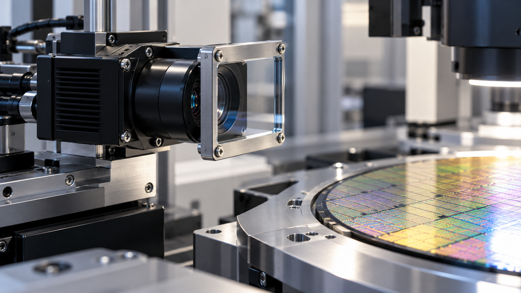
A protective window positioned between the camera or optical sensor and the wafer must transmit the required wavelength while maintaining stable optical geometry.
If the window bends under mounting force, introduces local wavefront distortion, reflects unwanted light or develops edge damage, inspection performance can suffer.
Rectangular sapphire windows are particularly useful when the optical field of view, equipment housing or camera geometry does not match a circular aperture.
Typical applications include wafer inspection systems, machine-vision cameras, process monitoring equipment, optical metrology modules, plasma chamber observation ports and semiconductor automation equipment.
However, rectangular geometry introduces engineering challenges that are different from those of a circular window.
The most important considerations include:
surface flatness, aspect ratio, edge strength, corner geometry, thickness, mounting stress, clear aperture and optical coating.
This article explains how these parameters should be specified when designing rectangular sapphire windows for semiconductor inspection and machine-vision equipment.
Why Use a Rectangular Sapphire Window?
Circular windows are convenient to manufacture and mount, but many semiconductor optical systems are naturally rectangular.
A camera sensor is rectangular.
A line-scan camera may require a long narrow optical aperture.
A machine-vision module may view a wide conveyor or wafer region.
A process chamber may provide only a narrow rectangular observation opening.
In these situations, using a circular window can waste space or unnecessarily increase component size.
A rectangular sapphire window allows the optical aperture to follow the actual field of view more closely.
For example, instead of using a large circular window to provide a 60 × 20 mm viewing area, the system may use a rectangular window designed around the required aperture.
This can reduce the overall envelope while maintaining adequate optical access.
Why Sapphire Is Used
Sapphire is single-crystal aluminum oxide, Al₂O₃.
It offers a useful combination of optical, mechanical and thermal properties.
For semiconductor equipment, its most important advantages include high surface hardness, good wear resistance, chemical resistance, high-temperature capability and transmission from the UV into the infrared, depending on grade and coating.
This makes sapphire particularly attractive when the optical window is exposed to conditions that might damage conventional optical glass.
Examples include repeated cleaning, airborne particles, process residues, mechanical contact and harsh equipment environments.
Sapphire is extremely hard, but hardness should not be confused with complete resistance to fracture.
It remains a brittle single-crystal material.
Therefore, edge condition, corner geometry and mounting method remain critical.
Flatness Directly Affects Optical Performance
Surface flatness is one of the most important specifications for an optical sapphire window.
An ideal inspection window would behave like a perfectly flat transparent plate.
A real window always contains some deviation from the ideal plane.
If that deviation becomes too large, the transmitted optical beam can be altered.
For machine vision, possible consequences include changes in focus, local image distortion or measurement error.
For laser metrology and interferometric systems, the effect can be even more significant.
A rectangular window should therefore not be specified only by:
length × width × thickness.
Its optical flatness must also match the inspection requirement.
Flatness Is Normally Specified Over a Defined Area
Optical flatness is often expressed relative to wavelength.
Typical drawing requirements may use values such as:
λ
λ/2
λ/4
λ/10
at a specified reference wavelength.
A tighter number generally represents a more precise optical surface.
However, the specification is incomplete unless the measurement aperture is defined.
For example:
Flatness: λ/4 over clear aperture at 632.8 nm
is more meaningful than simply:
Flatness: λ/4.
The distinction becomes particularly important for rectangular optics because the corners and edge regions may be more difficult to polish and support than the central area.
Clear Aperture Should Be Defined Separately
The physical size of the sapphire window and its optical clear aperture are not necessarily the same.
Consider a rectangular component measuring:
80 × 40 mm
The equipment may only require optical performance over:
72 × 34 mm
The remaining border can be reserved for:
mounting, sealing, beveling and edge support.
This approach can make the component easier to manufacture and install.
It can also prevent the mounting hardware from interfering with the active field of view.
A useful drawing therefore defines both:
| Parameter | Example |
|---|---|
| Overall size | 80 × 40 mm |
| Thickness | 3 mm |
| Clear aperture | 72 × 34 mm |
| Surface flatness | Defined over clear aperture |
| Surface quality | Defined over clear aperture |
| Edge region | Mounting / bevel area |
This distinction is particularly useful in machine-vision systems.
Transmitted Wavefront Can Be More Important Than Surface Flatness
Two surfaces may each meet a flatness specification while the complete window still changes the transmitted wavefront.
Transmitted optical performance can be influenced by:
surface geometry, thickness variation, refractive-index behavior, internal material characteristics and mechanical stress.
For basic camera protection, surface flatness may be sufficient.
For high-precision wafer metrology, the engineer may also need to specify transmitted wavefront distortion.
This is especially important when the window is located in a collimated beam or between precision imaging optics and the wafer.
The correct specification should therefore follow the optical architecture.
Rectangular Windows Behave Differently From Circular Windows
A circular window has rotational symmetry.
A rectangular window does not.
Its mechanical behavior depends on:
length, width, thickness, support position and pressure direction.
A long rectangular plate may flex differently along its long axis and short axis.
Therefore, the ratio between length and width becomes important.
This is commonly described as the aspect ratio.
For example:
50 × 50 mm
has an aspect ratio of 1:1.
100 × 20 mm
has an aspect ratio of 5:1.
These two windows should not automatically use the same thickness or mounting approach even if their surface area is similar.
High-Aspect-Ratio Windows Need Additional Attention
Long, narrow sapphire windows are useful for:
line-scan cameras, elongated machine-vision apertures, laser scanning systems and narrow equipment viewports.
However, increasing the aspect ratio can increase sensitivity to bending and mounting stress.
Imagine a long rectangular window supported only at its two short ends.
The central region can behave differently from a compact square window supported around its full perimeter.
Important factors include:
unsupported span, window thickness, mounting pressure, external pressure and temperature.
A high-aspect-ratio design should therefore be reviewed mechanically rather than simply scaling a smaller window.
Thickness Must Be Selected for Both Optical and Mechanical Requirements
A thinner sapphire window offers several potential advantages.
It reduces mass.
It reduces the optical path length through sapphire.
It may simplify compact equipment design.
However, a thinner window is also more sensitive to mechanical loading and mounting distortion.
A thicker window generally provides higher rigidity but can introduce other considerations.
These include increased material cost, greater optical path length, higher mass and potentially more difficult thermal equalization.
The correct thickness should therefore balance:
mechanical stability + optical performance + environment + mounting method.
There is no universal thickness for a rectangular sapphire window.
Edge Strength Is Critical
One of the most important differences between optical performance and mechanical reliability occurs at the window edge.
The central polished area may be nearly perfect while a small edge chip becomes the location where fracture begins.
Sapphire is strong and extremely hard, but like other brittle materials, its effective strength is strongly influenced by surface and edge defects.
For rectangular windows, this becomes especially important because there are:
four long edges and four corners.
Each creates an opportunity for stress concentration or handling damage.
Sharp Corners Should Be Evaluated Carefully
A theoretical rectangle has perfectly sharp 90-degree corners.
That geometry is not always desirable for a brittle optical component.
Sharp corners can be more vulnerable during:
machining, cleaning, coating, shipping and equipment assembly.
Depending on the mechanical design, engineers may use:
small corner radii, corner chamfers or controlled edge breaks.
For example, instead of specifying a perfectly sharp corner, a drawing might permit:
R0.5 mm
or another application-appropriate radius.
This small change can sometimes improve manufacturability and durability significantly.
However, the corner radius should not interfere with the equipment aperture or gasket geometry.
Protective Bevels Help Reduce Chipping
Optical sapphire windows commonly use a protective edge bevel.
The bevel removes the extremely sharp intersection between the polished face and the sidewall.
This can help reduce accidental chipping during handling and mounting.
The bevel might be specified as:
0.2–0.5 mm × 45°
or another drawing-specific geometry.
The exact value should depend on window thickness and optical clear aperture.
A large bevel on a small thin window can consume too much optical area.
Therefore:
bevel size + clear aperture + overall dimensions
should be designed together.
Edge Finish Matters
Edges can be supplied in different conditions depending on the application.
Possible treatments include fine-ground edges, polished edges and specially machined mounting profiles.
For many semiconductor machine-vision windows, a fine-ground protected edge can be adequate.
More demanding mounting or sealing designs may require additional precision.
A poorly finished edge can increase the likelihood of:
chipping, microcracking or particle generation.
Therefore, an RFQ should not specify only the major optical surfaces.
The edge treatment should also be defined.
Why Rectangular Sapphire Windows Can Crack During Mounting
A sapphire window may pass incoming inspection and still crack after installation.
One common cause is excessive or uneven mounting force.
For example, imagine a rectangular frame tightened using four screws.
If one screw applies significantly more force than the others, the sapphire can experience local bending.
A similar problem can occur when the mounting surface is not flat.
The window is then forced to conform to the distorted frame.
Because sapphire is rigid, this can generate significant localized stress.
The mounting system should therefore support the optic without trying to mechanically reshape it.
Do Not Use the Window to Correct Housing Flatness
This is an important equipment-design principle.
If the metal housing is not flat, tightening a sapphire window against it should not be used to compensate for the error.
The window may visually appear seated, but internal stress can remain.
This can produce:
optical distortion, stress-induced birefringence effects, edge damage or eventual fracture.
The mating surface should instead be manufactured with appropriate flatness.
A compliant sealing or mounting layer may also be used where compatible with the process.
Full-Perimeter Support vs Point Clamping
A rectangular window can be mounted in several ways.
A full-perimeter frame distributes load around the edge.
Point clamps apply force at selected locations.
A retaining plate can distribute the preload over a broader area.
The most appropriate method depends on:
vacuum conditions, pressure difference, temperature, cleanliness and maintenance requirements.
For many optical systems, uniformly distributed support is preferable to concentrated point loading.
However, the mount must also avoid contaminating or covering the clear aperture.
Gasket Selection Matters
A gasket or compliant mounting layer can reduce direct hard contact between sapphire and metal.
It may also provide sealing.
However, the material must be compatible with the equipment environment.
Important considerations include:
vacuum compatibility, outgassing, temperature resistance, compression set, particle generation and chemical resistance.
A gasket suitable for an ordinary industrial camera enclosure may not be appropriate for a semiconductor process chamber.
Thermal Expansion Mismatch Must Be Considered
Sapphire and metal housings do not expand at the same rate.
During temperature changes, the metal frame may attempt to expand more or less than the window.
If the window is rigidly constrained, thermal stress can develop.
The mount should therefore allow controlled differential expansion where temperature variation is significant.
This may be accomplished through:
clearance, compliant seals or controlled preload.
The exact strategy depends on the temperature range and equipment construction.
Mounting Can Change Optical Flatness
A sapphire window may meet a flatness requirement when measured in a free state.
After installation, excessive mounting force can bend the component.
The installed optical surface may therefore differ from the incoming inspection result.
For high-precision wafer inspection equipment, this distinction can be important.
The engineer should consider:
free-state flatness
and
mounted-state optical performance
as separate concepts.
Prototype testing should ideally evaluate the window in the actual fixture.
Machine Vision Is Sensitive to Window Tilt
A rectangular window should also be installed with controlled angular alignment.
If the entire window is tilted relative to the optical axis, it may shift the image or beam.
The effect depends on:
thickness, refractive index, angle and optical geometry.
For ordinary imaging, a small tilt may be acceptable.
For telecentric measurement systems or laser-based dimensional inspection, the acceptable angular error may be much smaller.
Mounting references should therefore be designed according to the required system accuracy.
Parallelism Between Optical Surfaces
A conventional rectangular protective window normally uses nearly parallel major surfaces.
Poor parallelism can introduce beam deviation.
In camera systems, this may create a small optical offset.
In precision metrology, it can affect calibration.
Parallelism can be specified in:
arcminutes or arcseconds.
The tighter the requirement, the more demanding fabrication and inspection become.
Do not specify extremely tight parallelism unless the optical system actually needs it.
Machine-Vision Imaging and Surface Quality
Surface defects such as scratches and pits scatter light.
For inspection systems, scattered light may reduce contrast or introduce unwanted background signal.
Surface quality is often specified using scratch-dig values such as:
60-40
40-20
20-10
10-5
The required grade depends on the optical system.
A camera protecting against industrial contamination may not require the same surface quality as a laser interferometer.
For wafer inspection, the decision should consider:
illumination geometry, camera resolution, numerical aperture and defect-detection sensitivity.
Better Surface Quality Is Not Always Better Economics
It may seem logical to specify 10-5 surface quality for every semiconductor window.
But this can increase manufacturing cost substantially.
If the machine-vision system is detecting relatively large package defects under diffuse illumination, such a specification may provide no measurable benefit.
On the other hand, high-resolution laser or dark-field inspection may be much more sensitive to scattering.
Therefore, the correct question is:
What defect level on the window begins to interfere with the inspection system?
The optical specification should be built from that requirement.
AR Coating Can Improve Machine-Vision Contrast
Sapphire has a relatively high refractive index.
As a result, uncoated surfaces reflect part of the incident light.
In an imaging system, those reflections can reduce transmitted intensity and potentially contribute to ghost images or stray light.
Anti-reflection coating can reduce these losses.
The coating should be designed around the illumination wavelength.
Typical inspection systems may operate with:
visible light, near-infrared, SWIR or laser wavelengths.
A generic AR coating should not automatically be assumed to work for all of them.
Modern Wafer Inspection May Use Multiple Wavelengths
Modern inspection equipment increasingly combines different imaging technologies.
A single platform may include conventional visible imaging together with infrared or 3D measurement.
In such systems, the window coating must support the required wavelength range.
For example, a coating optimized only for the visible spectrum may reduce performance if the inspection module also uses near-IR or SWIR imaging.
The equipment designer should therefore provide the complete spectral requirement before selecting the coating.
Coating Should Match the Angle of Incidence
AR coating performance depends not only on wavelength but also on the angle at which light reaches the surface.
For near-normal machine vision, this may be relatively straightforward.
For angled illumination, dark-field systems or oblique laser measurement, the coating may need to be optimized for a specific AOI.
Important RFQ information therefore includes:
wavelength + AOI + polarization where relevant.
Crystal Orientation
Because sapphire is a single crystal, its optical properties are anisotropic.
Crystal orientation can therefore matter in precision optical applications.
C-plane sapphire is commonly used for optical windows.
However, the best orientation depends on the specific optical and mechanical requirements.
For ordinary machine vision, orientation may not dominate system performance.
For polarization-sensitive or precision laser measurement, it should be considered more carefully.
Aspect Ratio and Crystal Orientation Are Different Issues
A long rectangular window may be cut in different directions relative to the sapphire crystal axes.
Therefore, two windows with the same:
length, width and thickness
may not be identical if crystallographic orientation differs.
For most standard protective applications this may not be critical.
For highly demanding optical or mechanical systems, the relationship should be defined.
Line-Scan Inspection Is a Natural Application
Rectangular sapphire windows are particularly suitable for line-scan camera systems.
A line-scan sensor typically requires a long optical field in one direction and a relatively narrow field in the other.
A long rectangular window can closely match this geometry.
Potential applications include:
wafer-edge inspection, substrate inspection, semiconductor package inspection and high-speed surface scanning.
For these designs, high aspect ratio and mounting stability become especially important.
Wafer Edge Inspection
Wafer edge inspection systems examine areas including:
bevel, edge exclusion region and near-edge surface defects.
The optical path may use multiple cameras or illumination angles.
A rectangular sapphire window can provide a protected optical interface while preserving the elongated field required by the imaging system.
In this application, the designer should pay particular attention to:
stray reflections, surface quality, clear aperture and angular alignment.
Top-Surface Wafer Inspection
For top-surface inspection, a window may protect cameras or optics from the handling environment.
High-resolution systems may inspect:
particles, scratches, pits, pattern abnormalities and contamination.
If the window introduces distortion or contamination, the inspection algorithm may incorrectly classify optical artifacts as wafer defects.
Window cleanliness and optical stability therefore become part of the measurement system.
Keep the Window Outside the Depth-of-Field Problem
Machine-vision systems have a finite depth of field.
A protective window changes the optical path.
Its position should therefore be included in the optical design from the beginning.
Adding a thick sapphire plate to an already calibrated imaging system can change focus or aberration behavior.
The window is not simply a mechanical accessory.
It is part of the optical path.
Cleanliness Is Essential
A high-quality sapphire window can become useless if its surface is contaminated.
Possible contaminants include:
particles, fingerprints, polishing residue, packaging debris and process deposits.
For semiconductor equipment, cleaning and packaging requirements should therefore be defined.
Depending on the application, parts may require controlled cleaning and clean packaging before installation.
The correct process depends on both the optical coating and equipment cleanliness requirement.
Avoid Touching the Clear Aperture
Even though sapphire is extremely scratch resistant, coated optical surfaces should be handled like precision optics.
Fingerprints and particles can affect image quality.
Installation procedures should therefore use appropriate handling methods and avoid unnecessary contact with the clear aperture.
Mechanical fixtures should preferably contact only the designated mounting border.
Edge Chips Should Have an Acceptance Standard
The statement:
“No edge chips.”
may be difficult to interpret in manufacturing.
A better drawing defines:
acceptable chip size, location and whether the requirement applies inside or outside the clear aperture.
For example, a very small chip on a nonfunctional outer mounting edge may have no effect on optical performance.
A similar defect extending into the active aperture could be unacceptable.
Clear acceptance criteria reduce disagreement between supplier and customer.
Corner Defects Require Special Attention
Rectangular optics have four corners, and these areas can be vulnerable during processing.
Inspection should therefore examine each corner for:
chips, cracks and excessive bevel variation.
For a part that is inserted tightly into a rectangular frame, corner clearance should also be provided.
The sapphire should not be forced into the housing because of an overly sharp metal corner radius.
Housing Corner Radius Must Match the Sapphire
This is a common mechanical-design issue.
If the sapphire window has:
R0.5 corners
but the machined pocket has:
R1.0 internal corners
the part may not fit fully into the recess.
Conversely, if the window has very sharp corners and the pocket is oversized, positioning may become inconsistent.
The optical drawing and mechanical housing drawing should therefore be reviewed together.
Pressure and Vacuum Windows
Some rectangular sapphire windows separate two different pressure environments.
For example:
vacuum chamber inside
and
atmosphere outside.
The pressure differential creates bending stress in the window.
For these applications, thickness should be determined through engineering analysis based on:
window dimensions, unsupported aperture, mounting method, pressure differential and safety factor.
A thickness selected for a small circular window should not automatically be applied to a large rectangular window.
Unsupported Aperture Is More Important Than Overall Size
Consider two windows with the same outer dimensions.
Window A is supported around a wide perimeter.
Window B has almost the entire surface unsupported.
The mechanical stress will not be the same.
Therefore, for vacuum or pressure design the critical dimensions include:
unsupported length × unsupported width
not merely the external sapphire size.
The RFQ should provide the actual mounting configuration where mechanical loading is significant.
Do Not Use Generic Pressure Ratings
A statement such as:
“3 mm sapphire can withstand X pressure”
is potentially misleading without specifying the geometry.
Mechanical performance changes substantially with:
size, aspect ratio, support method, edge quality and pressure direction.
For safety-critical pressure applications, proper mechanical calculation and validation should be performed for the actual assembly.
Large Rectangular Sapphire Windows
As dimensions increase, several manufacturing and system-level issues become more important.
These include:
material availability, flatness, polishing uniformity, thickness, edge strength and mounting stress.
A large sapphire plate with excellent optical polish may still distort after installation if the mounting frame is not sufficiently flat.
For large-area semiconductor equipment windows, the optical component and housing should therefore be developed together.
Recommended RFQ Parameters
A useful custom rectangular sapphire-window specification might include:
| Parameter | Information to Provide |
|---|---|
| Application | Wafer inspection / machine vision / metrology |
| Material | Optical-grade sapphire |
| Crystal orientation | C-plane or specified orientation |
| Length | Nominal + tolerance |
| Width | Nominal + tolerance |
| Thickness | Nominal + tolerance |
| Corner geometry | Sharp / radius / chamfer |
| Edge finish | Fine ground / polished |
| Protective bevel | Size and angle |
| Clear aperture | Dimensions or percentage |
| Surface flatness | Requirement + measurement wavelength |
| Parallelism | Required value |
| Surface quality | Scratch-dig |
| Surface roughness | If required |
| Transmitted wavefront | If required |
| Coating | Uncoated / AR / BBAR |
| Wavelength | Operating range |
| Angle of incidence | If applicable |
| Environment | Atmospheric / vacuum / plasma / high temperature |
| Pressure differential | If applicable |
| Mounting method | Frame / gasket / retainer |
| Quantity | Prototype / production |
Example Specification
A practical inquiry could read:
Product: Rectangular Sapphire Optical Window
Application: 300mm Wafer Machine-Vision Inspection
Material: Optical-Grade Sapphire
Crystal Orientation: C-Plane
Size: 80.00 × 40.00 mm
Thickness: 3.00 mm
Corner Radius: R1.0 mm
Clear Aperture: 72 × 34 mm minimum
Surface Quality: 20-10 scratch-dig
Flatness: According to optical drawing
Parallelism: Customer specified
Edges: Fine ground
Bevel: Protective bevel
Coating: AR both surfaces
Wavelength: 450–700 nm
Environment: Clean semiconductor equipment
Mounting: Perimeter-supported frame
Quantity: 5 pcs qualification followed by production
This provides much more useful information than simply requesting:
“80 × 40 × 3 mm sapphire glass.”
Prototype the Window Together With the Mount
For a new semiconductor inspection system, it is useful to qualify not only the sapphire component but also the complete installed assembly.
Prototype testing can examine:
image sharpness, distortion, stray reflection, window deflection, mounting stress, thermal behavior and cleaning durability.
The same sapphire window can behave differently in two different fixtures.
Therefore, if image quality changes unexpectedly after installation, the problem should not automatically be attributed to polishing quality.
The mount should also be investigated.
Questions to Ask a Sapphire Window Manufacturer
Before ordering a custom rectangular window, engineering teams should confirm whether the supplier can control the required overall dimensions, corner radius, protective bevel, flatness, parallelism, surface quality and coating.
It is also useful to confirm how the optic will be supported during polishing and inspection, how edge chips are controlled, how clear aperture is defined, whether crystal orientation can be documented, and whether final inspection data can be provided.
For pressure-loaded or unusually high-aspect-ratio parts, the actual mounting configuration should be discussed before finalizing thickness.
Design Principle: Treat the Window and Mount as One Optical System
The most important principle is that a rectangular sapphire window should not be designed in isolation.
Its performance depends on the relationship between:
sapphire geometry + optical specification + mounting frame + illumination + camera + operating environment
Flatness affects transmitted image quality.
Aspect ratio affects mechanical behavior.
Edge and corner quality influence fracture resistance.
Mounting force can distort an otherwise precise optical surface.
AR coating affects transmission and stray reflection.
And cleanliness directly affects defect detection.
For this reason, the window should be included in optical and mechanical design from the beginning rather than added after the camera system has already been finalized.
Conclusion
Rectangular sapphire windows can provide a durable optical interface for semiconductor wafer inspection, machine vision and metrology systems.
Their advantage is not simply that sapphire is hard.
A successful component requires coordinated control of:
flatness + aspect ratio + thickness + edge strength + corner geometry + clear aperture + coating + mounting stress
For high-resolution inspection systems, surface flatness and transmitted optical quality help preserve accurate imaging.
For long or large rectangular windows, aspect ratio and unsupported span must be considered when selecting thickness.
Protective bevels and controlled corner radii can improve edge durability.
And the mounting structure must distribute load without forcing the sapphire to conform to an imperfect housing.
The best RFQ therefore goes well beyond:
length × width × thickness.
It should define the optical aperture, surface specifications, edge geometry, crystal orientation, coating, operating wavelength, mounting environment and mechanical loading.
When these factors are designed together, rectangular sapphire windows can serve as reliable long-life optical interfaces for advanced wafer inspection and semiconductor machine-vision equipment.