
Sapphire windows are widely used in optical instruments, semiconductor processing equipment, high-pressure viewports, infrared systems, protective sensor covers and harsh-environment imaging systems. Their popularity comes from sapphire’s high hardness, mechanical strength, chemical stability and broad optical transmission range.
However, the performance of a sapphire window is not determined by the material alone. Two windows made from the same sapphire grade and with the same dimensions may perform very differently if their surface quality, flatness or parallelism specifications are different.
For engineers and procurement teams, three parameters are especially important:
- Scratch-dig
- Surface flatness
- Parallelism
These parameters describe different aspects of optical quality. Scratch-dig controls localized cosmetic defects, flatness controls the overall shape of an optical surface, and parallelism controls the angular relationship between the two main surfaces.
Understanding the differences between them is essential when specifying sapphire windows for imaging, laser, sensing, vacuum, semiconductor and precision optical applications.
1. Why Surface Quality Matters for Sapphire Windows
A sapphire window normally performs two functions. First, it provides mechanical or environmental protection. Second, it allows light to pass through with an acceptable level of distortion, scattering and reflection.
Surface defects or geometric errors can negatively affect both functions.
Scratches and pits may scatter light, increase stray light and reduce the visual quality of the component. Poor flatness may distort the transmitted wavefront. Insufficient parallelism may cause beam deviation, image displacement or unwanted interference effects.
These problems become more significant in applications involving:
- Coherent laser beams
- High-resolution imaging
- Interferometric measurement
- Narrow optical fields
- High-power illumination
- Precision alignment
- Multiple optical surfaces
- High numerical-aperture systems
A protective sapphire cover for an industrial camera may not require the same optical quality as a sapphire window used in an interferometer or laser cavity. Therefore, surface specifications should always be selected according to the actual function of the window.
2. Scratch-Dig: Evaluating Localized Surface Imperfections
Scratch-dig is one of the most commonly used methods for specifying the visible surface quality of optical components.
The term describes two categories of localized defects:
- Scratches: elongated defects or marks on the polished surface
- Digs: localized pits, pinholes, bubbles, inclusions or small circular defects
Scratch-dig inspection is commonly associated with the comparison-based system described in MIL-PRF-13830. This specification covers the manufacture and inspection of finished optical components, including windows, lenses, prisms and mirrors.
ISO 10110-7 provides another internationally recognized system for specifying acceptable surface imperfections within a defined test region. It covers localized imperfections, edge chips and long scratches on individual optical elements and assemblies.
It is important to recognize that the MIL-style scratch-dig notation and ISO surface-imperfection notation are not identical systems. A drawing or purchase order should therefore state which standard and inspection method apply.
3. How to Read a Scratch-Dig Specification
A typical scratch-dig requirement may be written as:
60-40
The first number refers to the allowable scratch designation, while the second number refers to the allowable dig designation.
Common specifications include:
| Scratch-Dig Grade | General Quality Level | Typical Applications |
|---|---|---|
| 80-50 | Commercial quality | Protective covers, general observation windows |
| 60-40 | Standard optical quality | Industrial optics, sensors, general imaging |
| 40-20 | Precision optical quality | Scientific instruments, higher-resolution imaging |
| 20-10 | High-precision quality | Laser systems, interferometry, demanding imaging |
| 10-5 | Very high optical quality | Specialized laser and metrology systems |
A smaller number generally indicates a stricter surface-quality requirement.
However, these values should not automatically be interpreted as the exact physical width and diameter of every defect. In the traditional comparison-based scratch-dig system, scratches are evaluated primarily by comparison with reference standards under controlled illumination and observation conditions.
Therefore, scratch-dig inspection is partly a visual or comparative process rather than a direct surface-roughness measurement.
4. Scratch-Dig Is Not the Same as Surface Roughness
Scratch-dig and surface roughness are frequently confused, but they describe different surface characteristics.
Scratch-dig evaluates isolated defects such as:
- Polishing scratches
- Handling marks
- Small pits
- Edge-related imperfections
- Coating blemishes
- Localized inclusions
Surface roughness describes microscopic, closely spaced variations across the polished surface. It is normally expressed using parameters such as:
- Ra
- Rq
- RMS roughness
A sapphire window can have low surface roughness while still containing one visible scratch. Conversely, a surface may appear free of large scratches but still have microscopic roughness that increases optical scattering.
For laser, ultraviolet and short-wavelength applications, both scratch-dig and surface roughness may need to be controlled.
5. How Scratch-Dig Affects Optical Performance
Surface defects can interact with incident light through scattering, diffraction and local reflection.
In conventional imaging applications, a small number of minor surface defects may have little measurable effect on image quality. Nevertheless, they can become important when the optical system requires low stray light or high contrast.
In laser systems, localized defects may be more critical because they can:
- Scatter coherent light
- Generate unwanted diffraction patterns
- Increase background noise
- Create local absorption sites
- Reduce the laser damage resistance of coated surfaces
- Contribute to heating under high optical power
The actual effect depends on the defect size, location, illumination wavelength, optical power and position of the window within the system.
A defect near the edge of the clear aperture may be less significant than the same defect located at the center of the optical path. For this reason, drawings should define the clear aperture or effective test region rather than applying the same requirement indiscriminately to the entire physical surface.
6. Surface Flatness: Controlling the Shape of the Window
Flatness describes how much an optical surface deviates from an ideal plane.
Even when a sapphire window appears flat to the eye, its surface may contain small amounts of:
- Curvature
- Bow
- Power
- Irregularity
- Edge roll-off
- Local waviness
ISO 10110-5 establishes rules for indicating allowable surface-form deviation on optical drawings. The current ISO framework allows surface-form tolerances to be expressed in physical units such as nanometres, while fringe-based specifications may also be used when the reference wavelength is clearly stated.
Flatness is often specified in fractions or multiples of a wavelength, such as:
- 2λ
- 1λ
- λ/2
- λ/4
- λ/10
The wavelength is commonly referenced to a helium-neon laser wavelength near 632.8 nm, but this must be explicitly stated because the physical deviation represented by a wave specification depends on the test wavelength.
For example, a flatness specification of λ/4 at 632.8 nm represents a stricter physical tolerance than λ/2 at the same wavelength.
7. What Does λ/4 Flatness Actually Mean?
When flatness is specified as λ/4, the interpretation must be linked to the measurement setup and whether the value refers to surface deviation or reflected wavefront deviation.
For a reflective measurement, the optical path difference can be approximately twice the physical surface-height error because the light travels to the surface and back. This distinction can create confusion when specifications are exchanged between designers, suppliers and inspection departments.
Therefore, a complete flatness requirement should ideally include:
- The allowable flatness value
- The reference wavelength
- The measurement aperture
- Whether the value refers to surface form or wavefront error
- The evaluation method
- Any excluded edge zone
Without these details, two inspection teams may interpret the same λ-based requirement differently.
8. How Sapphire Window Flatness Is Measured
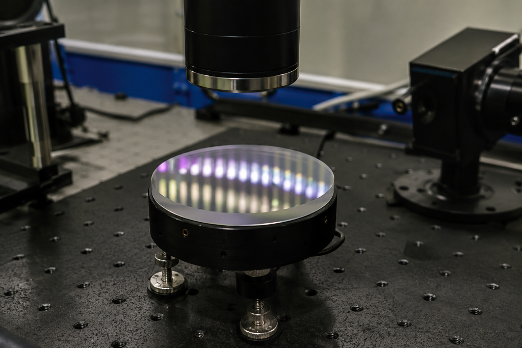
Flatness is commonly measured using optical interferometry.
In a typical test, the sapphire surface is compared with a calibrated reference flat. When monochromatic light reflects from the test surface and reference surface, interference fringes are formed.
The shape and spacing of these fringes indicate the difference between the surfaces.
Straight, evenly spaced fringes generally indicate a relatively uniform difference in angle or spacing. Curved or irregular fringes indicate surface-form errors.
NIST describes optical-flat calibration methods based on direct interferometric comparison with a master flat and absolute three-flat methods. These techniques demonstrate why the accuracy of the reference surface, support condition and measurement setup is important in precision flatness inspection.
Modern phase-shifting interferometers can generate a full surface map and calculate values such as:
- Peak-to-valley deviation
- RMS surface error
- Power
- Irregularity
- Astigmatism
- Local surface deformation
For transparent sapphire windows, measurement can be complicated by reflections from both the front and rear surfaces. Appropriate measurement geometry, surface separation, wavelength selection or data-processing methods may be required to isolate the surface being tested.
9. Factors That Influence Flatness Measurement
Flatness is not only a manufacturing property. It can also be influenced by the inspection environment.
Important factors include:
Support Method
A thin sapphire window may deform under its own weight or due to clamping pressure. Measuring it on a rigid fixture may produce a different result from measuring it in a free or lightly supported condition.
Temperature
Temperature gradients can cause temporary deformation. Sapphire also has anisotropic material properties, meaning some physical characteristics depend on crystallographic orientation.
Surface Cleanliness
Dust, oil, fingerprints or particles between the window and test fixture may affect the interference pattern.
Clear Aperture
The edge region is often more difficult to polish and may contain roll-off. A flatness result across the full diameter may therefore differ significantly from a result measured only over the optical clear aperture.
Coating Stress
Anti-reflection or other functional coatings may introduce stress that changes the final surface form, particularly on thin windows.
For demanding applications, flatness should be verified after all major manufacturing operations, including coating when applicable.
10. How Flatness Affects Optical Performance
A window with poor flatness behaves like a weak lens or distorted optical element.
Instead of passing through without modification, the transmitted wavefront may acquire:
- Defocus
- Astigmatism
- Higher-order aberrations
- Local wavefront distortion
- Image blur
- Phase non-uniformity
The transmitted wavefront error depends on more than the flatness of one surface. It is influenced by:
- Front-surface form
- Rear-surface form
- Refractive index
- Thickness variation
- Parallelism
- Material homogeneity
- Crystal orientation
- Mounting stress
For this reason, transmitted wavefront error may be a more meaningful specification than individual surface flatness in some precision systems.
A component can have two relatively flat surfaces but still produce optical distortion if the surfaces, thickness distribution or internal refractive-index distribution interact unfavorably.
11. Parallelism: The Relationship Between Two Surfaces
Parallelism describes how closely the front and rear surfaces of a sapphire window remain parallel to each other.
It may be specified as:
- Angular deviation
- Wedge angle
- Thickness variation
- Total thickness variation
- Arcminutes
- Arcseconds
- Milliradians
- Microradians
A perfectly parallel window has zero wedge angle. In practice, every manufactured window has some finite deviation.
For general protective windows, a relatively loose parallelism tolerance may be acceptable. Precision laser, imaging and interferometric systems may require parallelism controlled to a few arcseconds or less.
12. Why Parallelism Matters
When a light beam passes through a plane-parallel window at an angle, it experiences lateral displacement. If the two surfaces are not parallel, the window behaves like a weak prism and introduces angular beam deviation.
This can cause:
- Beam pointing error
- Image displacement
- Alignment changes
- Focus shift across the aperture
- Chromatic angular deviation
- Uneven optical path length
- Difficulty replacing windows interchangeably
In a laser system, even a small angular error may become significant over a long propagation distance. A small beam deviation at the window can produce a much larger positional shift several metres away.
Parallelism is also important in imaging systems because wedge can create double images or ghost displacement caused by reflections from the two surfaces.
13. Parallel Windows and Unwanted Interference
Although high parallelism is desirable in many applications, extremely parallel surfaces can also form a weak Fabry–Pérot etalon.
Multiple reflections between the two surfaces may interfere and produce:
- Spectral fringes
- Intensity modulation
- Etalon effects
- Interference rings
- Measurement instability
For broadband imaging, these effects may be negligible. For narrow-linewidth lasers, spectroscopy or interferometric systems, they may become significant.
In such cases, designers may intentionally specify a small wedge rather than maximum parallelism. The wedge separates reflected beams and prevents them from overlapping coherently.
Therefore, the correct engineering requirement is not always “the highest possible parallelism.” It is the surface relationship that best suits the optical system.
14. How Parallelism Is Measured
Parallelism may be evaluated using several methods.
Mechanical Thickness Measurement
A precision thickness gauge or coordinate measurement system can measure thickness at multiple positions. The difference between maximum and minimum values provides total thickness variation.
This method is useful for manufacturing control, but it does not always provide the complete angular relationship between optical surfaces.
Interferometric Measurement
Interferometry can evaluate the relative geometry of the front and rear surfaces with high precision.
Autocollimator Measurement
Reflections from the two surfaces can be observed with an autocollimator. The angular separation between the reflected images can be used to determine wedge or parallelism.
Optical Beam-Deviation Measurement
A collimated beam passes through the window, and the change in beam angle or position is measured. This method directly evaluates the effect of the component on the optical path.
The selected method should match the tolerance level and functional requirements of the application.
15. Flatness and Parallelism Are Not the Same
Flatness and parallelism are related but independent.
A window may have:
- Two flat surfaces that are not parallel
- Two parallel surfaces that are both curved
- One flat surface and one distorted surface
- Good individual surface flatness but unacceptable transmitted wavefront error
Consider a wedge-shaped window. Both surfaces could be polished extremely flat, but because they are tilted relative to each other, the parallelism would be poor.
Conversely, two surfaces could have similar curvature and remain approximately parallel at every point. The parallelism may appear acceptable even though neither surface meets a strict flatness requirement.
Both parameters must therefore be specified separately when they are functionally important.
16. Typical Specification Levels for Sapphire Windows
The following values provide a general engineering reference rather than universal acceptance criteria.
| Application Level | Scratch-Dig | Flatness | Parallelism |
| General protective window | 80-50 or 60-40 | 2λ to 1λ | Several arcminutes |
| Industrial optical window | 60-40 | 1λ to λ/2 | 1–3 arcminutes |
| Precision imaging window | 40-20 | λ/2 to λ/4 | Less than 1 arcminute |
| Laser-grade window | 20-10 or better | λ/4 to λ/10 | Arcsecond-level control |
| Interferometric application | Application-specific | λ/10 or tighter | Application-specific |
The appropriate specification depends on diameter, thickness, aspect ratio, clear aperture, crystal orientation, coating condition and inspection method.
Large, thin sapphire windows are generally more difficult to manufacture and measure to extremely tight flatness tolerances than small, thick windows.
17. Avoiding Over-Specification
One of the most common procurement mistakes is requesting the strictest available values for every parameter.
For example, a buyer may specify:
- 10-5 scratch-dig
- λ/10 flatness
- A few arcseconds of parallelism
- Extremely low surface roughness
- Full-aperture inspection
- Tight dimensional tolerances
Such a window may be technically possible, but it can require additional polishing, interferometric correction, specialized handling, more extensive inspection and a lower manufacturing yield.
As a result, cost and lead time may increase substantially without providing a meaningful performance benefit.
A better specification process begins with the optical function:
- Determine the wavelength range.
- Define the clear aperture.
- Evaluate whether the window is used for protection, imaging, laser transmission or metrology.
- Calculate the allowable beam deviation or wavefront error.
- Determine whether stray light is critical.
- Consider whether a deliberate wedge is needed.
- Select only the tolerances required by the system.
18. Important Information to Include on a Sapphire Window Drawing
A complete technical drawing or request for quotation should include more than the basic diameter and thickness.
Recommended information includes:
- Outside dimensions
- Nominal thickness
- Thickness tolerance
- Sapphire crystal orientation
- Clear aperture
- Scratch-dig requirement
- Applicable surface-imperfection standard
- Flatness requirement
- Reference wavelength
- Parallelism or wedge tolerance
- Surface roughness
- Edge chamfer or bevel
- Edge-chip allowance
- Coating type
- Coating aperture
- Transmission wavelength range
- Environmental requirements
- Inspection and documentation requirements
The drawing should also state whether flatness and surface quality apply to both surfaces or only to the optical working surface.
19. Selecting Specifications by Application
Protective Sensor Covers
For protective covers used on industrial sensors, cameras or detectors, mechanical strength and durability may be more important than extremely tight optical tolerances.
A 60-40 or 80-50 surface-quality requirement and moderate flatness may be sufficient, depending on image resolution and aperture position.
High-Resolution Imaging
Imaging systems require better control of surface form and parallelism because wavefront distortion and wedge can reduce image quality.
Specifications such as 40-20 scratch-dig and λ/4 or λ/2 flatness may be appropriate, but transmitted wavefront error should also be considered.
Laser Windows
Laser applications often require strict scratch-dig, low surface roughness, suitable coating quality and controlled flatness.
The designer should also evaluate whether the surfaces should be parallel or intentionally wedged.
Vacuum and High-Pressure Viewports
Mechanical thickness and mounting design are primary considerations, but optical quality remains important when the viewport is used for observation, spectroscopy or laser access.
Flatness should be evaluated under realistic mounting and pressure conditions when deformation may affect optical performance.
Semiconductor Processing Equipment
Sapphire windows used in plasma, deposition, etching or inspection equipment may require a combination of optical quality, dimensional precision, cleanliness and resistance to chemical or plasma exposure.
The clear aperture, coating durability and allowable particle generation should be defined together with the optical tolerances.
20. Conclusion
Scratch-dig, flatness and parallelism describe three different aspects of sapphire window quality.
Scratch-dig controls localized imperfections such as scratches and pits. Flatness controls the deviation of each optical surface from an ideal plane. Parallelism controls the angular relationship between the front and rear surfaces.
None of these parameters should be evaluated in isolation.
A high-performance sapphire window requires a balanced specification that considers:
- Surface imperfections
- Surface form
- Surface roughness
- Thickness variation
- Wedge
- Transmitted wavefront error
- Coating performance
- Mounting conditions
- Optical wavelength
- Final application
The best sapphire window is not necessarily the one with the strictest numerical tolerances. It is the one whose optical, mechanical and dimensional requirements are correctly matched to the operating system.
By defining the applicable standard, clear aperture, measurement method and functional limits, engineers can reduce procurement ambiguity, avoid unnecessary manufacturing costs and obtain sapphire windows that provide reliable optical performance in real operating conditions.