
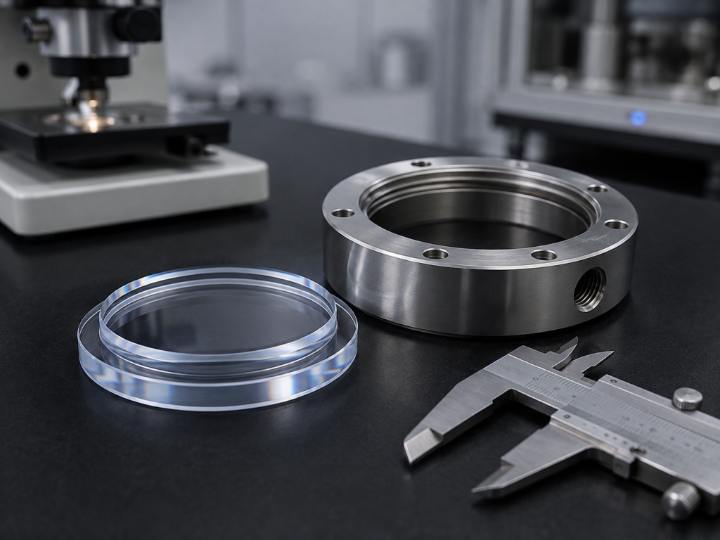
Stepped sapphire windows combine an optical transmission area with a precision-machined locating shoulder. Unlike a conventional flat disc, a stepped window has two or more diameters or thickness levels that allow the component to fit directly into a sensor body, metal housing, retaining structure or sealing assembly.
This geometry can reduce the number of separate mounting components and improve repeatable positioning. However, it also introduces manufacturing and inspection requirements that do not apply to standard sapphire windows.
The buyer must define the relationship between the main outside diameter, locating diameter, shoulder width, step depth, optical surfaces and finished edges. A stepped sapphire window can meet its individual diameter tolerances but still fail during assembly if its shoulder is too narrow, its step is not concentric or its corner geometry creates excessive local stress.
Single-crystal sapphire is selected for demanding optical parts because it combines optical transparency with hardness, rigidity, wear resistance, heat resistance and chemical resistance. These properties support its use in industrial machinery, semiconductor equipment, sensing systems and other harsh environments.
What Is a Stepped Sapphire Window?
A stepped sapphire window is an optical component with a change in diameter or thickness that creates a defined shoulder.
Common configurations include:
- A large optical flange with a smaller locating diameter
- A smaller optical face with a larger mounting flange
- A recessed central optical surface
- A raised central optical surface
- A stepped outer diameter
- A stepped inner opening
- A double-sided locating shoulder
- A sapphire window with both an external step and central hole
- A multi-level sapphire component for a custom housing
Depending on the design, the step may provide:
- Radial positioning
- Axial positioning
- A retaining surface
- A gasket seat
- An adhesive-bonding area
- A brazing or metallization zone
- Protection for the optical surface
- Alignment with a sensor or detector
- Controlled insertion depth
- Separation between optical and mechanical surfaces
The drawing should identify which feature provides the primary mechanical location and which surface performs the optical function.
Typical Applications
Stepped sapphire windows can be used in:
- Pressure and temperature sensors
- Optical sensor housings
- Infrared and ultraviolet instruments
- Camera protection assemblies
- Laser measurement equipment
- Vacuum chambers
- Gas-detection systems
- Medical and analytical instruments
- Semiconductor process equipment
- High-temperature observation ports
- Optical communication components
- Harsh-environment detector packages
Sapphire optical components are also used in vacuum equipment, reaction-furnace windows and optical communication parts where transparency, heat resistance and mechanical performance are required.
Important Stepped-Window Dimensions
A complete drawing should not describe the component only as a “stepped sapphire window.” Each functional dimension must be identified separately.
The principal dimensions normally include:
- Main outside diameter
- Locating or pilot diameter
- Overall thickness
- Step depth
- Shoulder width
- Optical aperture
- Edge bevel
- Internal corner radius
- External corner chamfer
- Concentricity between diameters
- Perpendicularity of the locating wall
- Parallelism between major surfaces
- Surface flatness
- Coating and masking boundaries
A cross-sectional drawing is especially important because a top view alone cannot clearly define the axial step geometry.
Main Outside Diameter
The largest outside diameter may perform several functions:
- Contacting a retaining ring
- Supporting a gasket
- Providing an adhesive-bonding flange
- Limiting insertion depth
- Carrying axial clamping force
- Defining the overall component size
The drawing should include the nominal diameter and tolerance.
For example:
Main outside diameter: Ø30.00 mm ±0.05 mm
The required tolerance should be based on the housing design and assembly method. A diameter used only as a non-contact outer boundary may not require the same tolerance as a diameter used for precision radial positioning.
Locating Diameter
The smaller stepped diameter is often inserted into a counterbore or precision-machined housing.
Its specification should include:
- Nominal diameter
- Diameter tolerance
- Roundness
- Cylindricity, when necessary
- Concentricity with the main diameter
- Surface finish
- Edge chamfer
- Engagement length
The locating diameter should not automatically be assumed to be optically polished. In many assemblies, a controlled fine-ground cylindrical surface is suitable for mechanical location or adhesive bonding.
Polishing should be requested when it provides a clear optical, sealing, cleanliness or wear-related benefit.
Shoulder Width
The shoulder is the annular surface connecting the larger diameter to the smaller locating section.
When the two diameters are concentric, the nominal radial shoulder width is:
Radial shoulder width = (large diameter − small diameter) ÷ 2
For example:
- Large diameter: 30 mm
- Small locating diameter: 24 mm
- Nominal radial shoulder width: 3 mm
The actual minimum shoulder width depends on:
- Diameter tolerances
- Concentricity tolerance
- Edge chamfers
- Corner radii
- Edge chipping
- Measurement uncertainty
A drawing should therefore evaluate the worst-case minimum shoulder width, not only the nominal value.
A shoulder that is too narrow may provide insufficient space for:
- Gasket contact
- Adhesive application
- Retaining-ring support
- Metallization
- Mechanical clamping
- Inspection
- Edge-strength margin
Step Depth
Step depth is the axial distance between the shoulder surface and the adjacent major surface.
It may determine:
- Insertion depth into the housing
- Optical-surface position
- Gasket compression
- Adhesive thickness
- Detector-to-window spacing
- Protection of the polished face
- Final assembly height
Step depth should be dimensioned from a clearly defined reference surface.
Possible specifications include:
- Step depth from the front optical surface
- Step depth from the rear mounting surface
- Remaining thickness beneath the shoulder
- Overall thickness plus local step depth
- Height of a raised optical section
Avoid defining the same axial geometry using several redundant dimensions unless reference dimensions are clearly marked. Conflicting dimension chains can create ambiguity during manufacturing and inspection.
Shoulder Flatness and Axial Seating
When the shoulder contacts a housing, retaining ring or gasket, its surface condition can affect how the sapphire sits in the assembly.
A poorly controlled shoulder may cause:
- Uneven seating
- Local rocking
- Non-uniform gasket compression
- Optical-axis tilt
- Point loading
- Adhesive-thickness variation
- Stress during tightening
The drawing should state whether the shoulder requires:
- Ground flatness
- Lapped flatness
- Optical polishing
- Surface-roughness control
- Parallelism with the optical face
- A defined sealing finish
Not every mounting shoulder needs an optical polish. A functional mechanical finish is often more appropriate unless the shoulder also serves as an optical or hermetic sealing surface.
Fit Tolerance Between Sapphire and Housing
The correct fit depends on the assembly method.
Common approaches include:
- Clearance fit
- Adhesive-bonded fit
- Gasket-supported fit
- Retaining-ring fit
- Metallized and brazed assembly
- Spring-loaded mounting
- Compliant seal assembly
Because sapphire is a hard but brittle crystalline material, a metal-style interference fit should not be selected without detailed mechanical and thermal analysis.
The fit must account for:
- Sapphire diameter tolerance
- Housing bore tolerance
- Assembly temperature
- Operating-temperature range
- Thermal-expansion difference
- Surface finish
- Housing roundness
- Coating or metallization thickness
- Adhesive bond-line thickness
- Required radial alignment
Clearance Fit
A clearance fit provides a small radial gap between the sapphire locating diameter and the housing bore.
Advantages may include:
- Easier assembly
- Lower insertion force
- Space for adhesive
- Accommodation of manufacturing tolerance
- Reduced risk of edge loading
However, too much clearance can allow:
- Radial movement
- Optical-axis decenter
- Uneven adhesive thickness
- Impact during vibration
- Misalignment of the clear aperture
The acceptable clearance should be calculated from the optical alignment and mechanical reliability requirements.
The drawing should not use only the statement “sliding fit.” It should specify the sapphire diameter and the mating housing limits.
Adhesive-Bonded Fit
For adhesive bonding, the radial gap must provide enough room for the selected adhesive while maintaining alignment.
The assembly design should consider:
- Adhesive viscosity
- Required bond-line thickness
- Curing shrinkage
- Operating temperature
- Chemical exposure
- Outgassing requirements
- Moisture resistance
- Repair or replacement requirements
The bonding area should be separated from the optical clear aperture whenever possible.
A controlled shoulder can provide an axial stop, while the locating diameter controls radial position. Adhesive may then be applied to the cylindrical wall, shoulder or both, depending on the design.
Gasket and O-Ring Assemblies
If the stepped sapphire window contacts a gasket or O-ring, the drawing should identify:
- Sealing surface
- Contact width
- Gasket location
- Expected compression
- Surface-finish requirement
- Allowable edge chamfer
- Maximum edge chipping
- Whether the shoulder carries axial load
A gasket should not be allowed to load a sharp or damaged sapphire edge.
The sealing surface should have enough uninterrupted width to accommodate positioning tolerance and gasket deformation without entering the optical aperture.
Concentricity Between Stepped Diameters
Concentricity is critical when one diameter locates the sapphire in the housing while another diameter defines the optical or sealing area.
Poor concentricity can cause:
- Uneven shoulder width
- Misalignment with the sensor
- Reduced sealing area on one side
- Coating-aperture offset
- Non-uniform assembly clearance
- Reduced edge-strength margin
- Partial obstruction of the optical beam
The drawing should define the primary datum and the controlled feature.
For example:
- Locating diameter defined as datum B
- Main outside diameter position controlled relative to datum B
- Optical clear aperture centered relative to datum B
- Optical surface controlled relative to primary face datum A
ISO 10110-6:2025 specifies drawing rules for centering and tilt tolerances for optical elements, subassemblies and assemblies.
Perpendicularity of the Step Wall
The cylindrical step wall should be sufficiently perpendicular to the reference surface when it controls insertion, alignment or sealing.
A tilted step wall can produce:
- Uneven radial clearance
- Partial contact with the housing
- Difficulty during insertion
- Optical-axis tilt
- Local stress
- Adhesive-thickness variation
Perpendicularity should be specified when it affects the final assembly rather than assumed from the diameter tolerance.
Internal Corner Geometry
The transition between the shoulder and the vertical step wall is one of the most important areas of a stepped sapphire component.
A perfectly sharp internal corner is difficult to manufacture and can create a local stress concentration.
Depending on the functional design, the transition may use:
- A controlled radius
- A relief groove
- A small chamfer
- A blended transition
- A specified maximum tool radius
The mating metal housing must provide clearance for the sapphire corner geometry.
For example, if the sapphire has an internal corner radius but the housing has a perfectly square counterbore, the two components may contact at the corner before the shoulder is fully seated.
The housing drawing and sapphire drawing should therefore be reviewed together.
Edge Strength and Stress Concentration
Stepped sapphire components contain more edges and transitions than conventional flat windows.
Potentially vulnerable regions include:
- Outer flange edge
- Locating-diameter edge
- Internal shoulder corner
- Transition between polished and ground surfaces
- Thin annular shoulders
- Areas near holes or slots
- Coating-mask boundaries
- Regions under retaining-ring load
As a general engineering principle, sharp geometry changes can increase local stress. For a sapphire window, risk can be reduced by:
- Avoiding unnecessary sharp internal corners
- Providing suitable edge chamfers
- Maintaining adequate shoulder width
- Preventing direct metal-to-edge loading
- Using compliant gaskets or adhesives where appropriate
- Controlling assembly torque
- Avoiding excessive interference
- Inspecting chips and cracks before assembly
- Supporting the component over a suitable area
- Accounting for differential thermal expansion
The exact geometry should be validated against the expected pressure, temperature, shock, vibration and mounting loads.
Edge Chamfers
Chamfers help remove fragile sharp corners and improve handling.
A stepped sapphire window may require separate specifications for:
- Front optical edge
- Rear optical edge
- Shoulder perimeter
- Locating-diameter edge
- Outer flange edge
- Internal transition edge
Example callouts may define:
- Chamfer width
- Chamfer angle
- Edge radius
- Maximum edge break
- Polished or ground finish
A general note such as “all edges chamfered” may be insufficient because different edges can have different functional requirements.
An oversized chamfer can reduce:
- Shoulder contact area
- Gasket width
- Optical clear aperture
- Bonding area
- Effective locating length
Edge Chipping
Edge chipping should be controlled separately at each functional zone.
Important inspection areas include:
- Optical clear aperture
- Sealing shoulder
- Locating diameter
- Internal step corner
- Non-functional outside edge
- Coated or metallized area
The drawing should define:
- Maximum chip size
- Permitted quantity
- Inspection magnification
- Whether chips may enter the clear aperture
- Whether chips are allowed on the sealing surface
- Different limits for functional and non-functional edges
A statement such as “no chips” is difficult to inspect consistently without a measurable acceptance limit.
Optical Surface Flatness
Stepped geometry can affect how the component is supported during grinding, lapping, polishing and inspection.
The optical drawing should define:
- Which face requires flatness control
- Test aperture
- Clear-aperture boundary
- Whether the shoulder is included
- Whether power is removed
- Reference wavelength, when fringe units are used
- Free-state or supported inspection condition
ISO 10110-5:2026 specifies rules for indicating surface-form deviation tolerances on optical drawings.
The optical surface and mechanical shoulder should not automatically be assigned the same flatness requirement. They perform different functions and may require different inspection methods.
Parallelism and Optical-Axis Tilt
The relationship between the front and rear optical surfaces can affect beam deviation and transmitted wavefront.
The drawing may need to specify:
- Parallelism
- Wedge
- Surface tilt
- Optical-axis relationship
- Shoulder parallelism
- Locating-wall perpendicularity
These controls should be separated clearly.
A component may have parallel optical faces but a shoulder that is not parallel to them. In this case, the window could sit at an angle in the housing even though its optical surfaces meet their individual specifications.
Clear Aperture and Mechanical Zones
A stepped sapphire window should distinguish between:
- Optical clear aperture
- Edge-exclusion zone
- Shoulder or mounting zone
- Adhesive-bonding area
- Gasket or sealing surface
- Coating aperture
- Locating diameter
- Non-functional edge area
The step should not intrude into the optical clear aperture unless the system is intentionally designed that way.
When a sensor is positioned behind the sapphire window, the clear aperture should include sufficient margin for:
- Sensor active-area tolerance
- Assembly decenter
- Housing tolerance
- Beam-angle variation
- Thermal movement
- Coating-mask tolerance
Coating Considerations
Stepped sapphire windows may receive:
- Anti-reflection coatings
- Conductive coatings
- Protective coatings
- Metallic edge coatings
- Patterned optical coatings
- Blackened perimeter treatments
The RFQ should state:
- Coated surface
- Wavelength range
- Angle of incidence
- Required transmission or reflectance
- Coating aperture
- Masking around the shoulder
- Whether the step wall may be coated
- Whether the bonding area must remain uncoated
- Acceptable overspray
- Coating-edge tolerance
The coating boundary should be referenced to the same datum system used for the optical and mechanical features.
Manufacturing Considerations
Stepped sapphire windows may require a combination of:
- Crystal orientation and blank preparation
- Outside-diameter grinding
- Step generation
- Corner-radius or chamfer machining
- Surface lapping
- Optical polishing
- Edge finishing
- Cleaning
- Coating
- Dimensional and optical inspection
Complex sapphire shapes require controlled lapping and polishing processes because sapphire combines high hardness and rigidity with optical-performance requirements.
Machining sequence can influence:
- Edge chipping
- Shoulder geometry
- Surface flatness
- Diameter tolerance
- Step depth
- Subsurface damage
- Final yield
The supplier should review tight mechanical tolerances together with optical requirements before confirming manufacturability.
Inspection Methods
A complete inspection plan may combine several measurement techniques.
Vision Measuring System
Suitable for checking:
- Main outside diameter
- Locating diameter
- Shoulder width
- Concentricity
- Chamfer dimensions
- Edge chipping
- Coating-mask position
Coordinate Measuring Machine
Suitable for:
- Step depth
- Shoulder height
- Diameter relationships
- Perpendicularity
- Datum-based position
- Complex stepped profiles
The probe strategy must avoid damaging polished sapphire edges.
Optical Comparator
Useful for evaluating:
- Cross-sectional profiles
- Chamfers
- Corner radii
- Shoulder geometry
- Edge condition
Interferometry
Suitable for:
- Optical surface flatness
- Transmitted wavefront
- Parallelism
- Surface-form analysis
Surface-Roughness Measurement
May be used for:
- Optical faces
- Mechanical shoulders
- Cylindrical locating surfaces
- Sealing areas
The measurement method should be appropriate for the required finish and surface geometry.
Microscopic Inspection
Suitable for:
- Edge chips
- Microcracks
- Scratches
- Digs
- Corner damage
- Coating defects
- Residue and particles
Recommended RFQ Information
| RFQ Item | Information to Specify |
|---|---|
| Sapphire orientation | C-plane, A-plane, M-plane or other |
| Overall shape | Round, rectangular or custom |
| Main outside diameter | Nominal value and tolerance |
| Locating diameter | Nominal value and tolerance |
| Overall thickness | Nominal value and tolerance |
| Step depth | Dimension and reference surface |
| Shoulder width | Nominal and minimum acceptable width |
| Concentricity | Relationship between stepped diameters |
| Perpendicularity | Step wall relative to reference face |
| Corner transition | Radius, chamfer or relief |
| Optical clear aperture | Size and location |
| Flatness | Value and test aperture |
| Parallelism or wedge | Maximum allowable value |
| Surface quality | Clear-aperture requirement |
| Shoulder finish | Ground, lapped or polished |
| Cylindrical-wall finish | Ground or polished |
| Edge chipping | Maximum size, quantity and zone |
| Coating | Wavelength, performance and aperture |
| Assembly method | Adhesive, gasket, retaining ring or brazing |
| Housing dimensions | Bore, counterbore and tolerances |
| Operating conditions | Temperature, pressure, shock and chemicals |
| Inspection report | Dimensional, optical or complete report |
| Quantity | Prototype and production volume |
Example Drawing Notes
An illustrative stepped sapphire window specification could include:
- Material: Optical-grade single-crystal sapphire
- Main outside diameter: Ø30.00 mm ±0.05 mm
- Locating diameter: Ø24.00 mm ±0.03 mm
- Overall thickness: 3.00 mm ±0.05 mm
- Step depth: 1.00 mm ±0.03 mm from rear mounting surface
- Locating diameter concentric with outside-diameter datum within 0.05 mm
- Step wall perpendicular to rear reference surface within the specified limit
- Controlled radius at internal shoulder transition
- Optical clear aperture: Ø22 mm minimum
- Surface quality: 20-10 within the clear aperture
- Flatness: specified over the clear aperture at the stated wavelength
- Shoulder surface: lapped mechanical finish
- Functional edges: controlled chamfer
- No chips above the specified limit on the optical or sealing areas
- AR coating on the front and rear optical surfaces
- Dimensional and optical inspection reports required
These values are illustrative only. Actual tolerances should be selected according to the sensor, housing, sealing method and operating conditions.
Common Specification Mistakes
Frequent drawing and RFQ problems include:
- Providing only an overall diameter and thickness
- Omitting step depth
- Not identifying the reference surface
- Specifying two diameters without concentricity
- Using “snug fit” without numerical housing limits
- Failing to define adhesive or gasket clearance
- Requiring a perfectly sharp internal corner
- Designing a housing corner that interferes with the sapphire radius
- Applying optical-polish requirements to all mechanical surfaces
- Making the shoulder too narrow for the gasket or retaining ring
- Omitting edge-chip limits at the internal step
- Allowing metal hardware to load a sharp sapphire edge
- Failing to define coating-mask boundaries
- Not considering differential thermal expansion
- Specifying flatness without a test aperture
- Ignoring assembly tolerance when defining the clear aperture
Conclusion
Stepped sapphire windows can integrate optical protection, mechanical location and sealing support into one precision component.
Their performance depends on more than the outside diameter and optical surface quality. A complete specification should define:
- Main diameter
- Locating diameter
- Step depth
- Shoulder width
- Concentricity
- Step-wall perpendicularity
- Internal corner geometry
- Fit clearance
- Optical clear aperture
- Flatness and parallelism
- Edge chamfers
- Edge-chipping limits
- Coating boundaries
- Inspection methods
The sapphire component and mating housing should be evaluated as one assembly.
Clear datum references, practical fit tolerances and controlled edge geometry can reduce assembly problems, protect the optical area and improve long-term reliability in sensor and industrial-housing applications.
FAQ
What is the purpose of the shoulder on a stepped sapphire window?
The shoulder can provide axial positioning, support a gasket or retaining ring, define insertion depth, create an adhesive area or separate the optical surface from the mechanical mounting zone.
Can a stepped sapphire window use an interference fit?
An interference fit can create high local stress in a brittle crystalline component. It should not be used without mechanical and thermal validation. Clearance, adhesive, gasket or compliant mounting methods are often easier to control.
Should the shoulder surface be optically polished?
Not necessarily. Optical polishing is appropriate when the shoulder performs an optical or specialized sealing function. A controlled ground or lapped surface may be more suitable for normal mechanical seating.
Why is the internal shoulder radius important?
A radius or controlled transition can improve manufacturability and reduce the severity of a sharp geometric transition. The mating housing must include enough corner clearance to allow the shoulder to seat properly.
How should the fit tolerance be specified?
Provide both the sapphire locating-diameter tolerance and the housing-bore tolerance. Also identify the assembly method, operating-temperature range, adhesive or gasket requirement and acceptable radial movement.
Can the step be located on the optical side?
Yes. A raised or recessed optical section can be produced, but the design must define the clear aperture, coating area, edge exclusion and inspection requirements for each level.
How is step depth inspected?
Step depth may be measured with a coordinate measuring machine, precision height measurement system, optical profilometer or another validated dimensional method suitable for the component geometry.