
Sapphire windows with precision through holes are specialized optical and protective components used in systems that require both transparent viewing and mechanical access through the same part. Unlike a standard flat sapphire window, this type of component contains one or more accurately machined holes for sensors, electrical feedthroughs, fluid channels, fasteners, optical fibers or mechanical alignment features.
Because sapphire is extremely hard, chemically stable and resistant to high temperatures, producing a clean and dimensionally accurate hole is significantly more challenging than drilling conventional glass. The hole diameter, edge quality, position tolerance, surface finish and remaining wall thickness must all be carefully controlled to prevent cracking and maintain the strength of the finished window.
This article explains the design principles, manufacturing methods, inspection requirements and typical applications of sapphire windows with through holes.
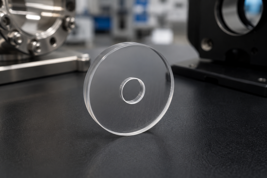
What Is a Sapphire Window with a Through Hole?
A sapphire window with a through hole is a transparent sapphire plate, disc, ring or custom-shaped component containing an opening that passes completely through the material.
The hole may be located:
- At the center of a round sapphire window
- Near the edge of the component
- In a square or rectangular sapphire plate
- In a stepped or recessed sapphire structure
- As part of a multi-hole pattern
- In combination with slots, grooves or countersunk features
These windows are commonly used when an optical system needs a protective transparent barrier while also allowing another component to pass through the window.
For example, a central hole may accommodate a sensor probe, optical fiber, electrode, shaft or gas inlet while the surrounding sapphire area protects the internal assembly from heat, pressure, abrasion or chemical exposure.
Why Sapphire Is Used for Windows with Holes
Sapphire is a single-crystal form of aluminum oxide. Its combination of optical, mechanical and thermal properties makes it suitable for demanding environments.
High Hardness and Wear Resistance
Sapphire has a Mohs hardness of approximately 9, making it highly resistant to scratches, abrasion and particle erosion. This is particularly useful in industrial systems where the window surface may be exposed to dust, slurry, repeated cleaning or mechanical contact.
Wide Optical Transmission Range
High-quality sapphire can transmit light from the ultraviolet region through the visible spectrum and into the infrared. The usable transmission range depends on material quality, thickness, surface finish and coating.
This allows a sapphire window with a hole to combine mechanical access with optical observation, illumination or sensing.
High Temperature Resistance
Sapphire retains useful strength at temperatures well above those tolerated by most conventional optical glasses. It is therefore used in furnaces, combustion systems, semiconductor equipment and high-temperature sensors.
Chemical Stability
Sapphire resists many acids, alkalis, solvents and process gases. This makes it suitable for chemical reactors, vacuum chambers, plasma systems and harsh laboratory environments.
High Mechanical Strength
When properly designed and mounted, sapphire can withstand pressure, impact and thermal cycling. However, machining a hole introduces a stress concentration, so the geometry must be carefully evaluated.
Common Shapes and Hole Configurations
Sapphire windows with holes can be manufactured in many different configurations.
Round Sapphire Windows with a Central Hole
This is one of the most common designs. The finished component resembles a transparent ring or washer.
Typical applications include:
- Optical sensor housings
- Pressure-resistant viewing ports
- Fiber feedthrough assemblies
- Mechanical shaft protection
- Vacuum equipment
- Laser and imaging systems
Square or Rectangular Sapphire Windows with Holes
Square and rectangular windows are often used in equipment housings, detector assemblies and custom optical modules.
The hole may be positioned at the center or offset according to the installation design.
Multiple-Hole Sapphire Windows
Some applications require two or more holes for:
- Multiple sensors
- Electrical contacts
- Gas channels
- Alignment pins
- Mounting screws
- Optical fibers
The distance between holes and the distance from each hole to the outer edge are critical design parameters.
Stepped Sapphire Windows with Through Holes
A stepped sapphire window may include a raised section, reduced-thickness area, shoulder or mounting flange. The through hole can be machined through one or more levels of the structure.
These designs are useful when the sapphire component must fit precisely into a metal, ceramic or polymer housing.
Countersunk or Chamfered Holes
A hole may include a chamfer, bevel or countersink to:
- Remove sharp edges
- Improve assembly
- Reduce chipping risk
- Accommodate a fastener
- Support adhesive or sealing material
- Reduce local stress concentration
The allowable countersink geometry depends on the sapphire thickness and hole diameter.
Key Design Considerations
A reliable sapphire window with a through hole begins with a practical design. The following factors should be reviewed before manufacturing.
Hole Diameter
Very small holes are more difficult to machine, clean and inspect. Small-diameter holes also increase the risk of edge chipping and taper.
The minimum achievable diameter depends on:
- Sapphire thickness
- Hole depth-to-diameter ratio
- Required diameter tolerance
- Hole position tolerance
- Edge quality requirements
- Machining method
- Production quantity
Designers should avoid specifying an unnecessarily small hole when a larger opening can perform the same function.
Sapphire Thickness
The thickness must be sufficient to provide mechanical strength around the hole. A thin sapphire window with a large hole may have a narrow remaining ring that is vulnerable to cracking.
Thicker material can improve strength but may increase:
- Material cost
- Machining time
- Optical path length
- Weight
- Internal reflection
- Difficulty of deep-hole machining
The final thickness should be selected based on pressure, mounting, temperature and optical requirements.
Distance from the Hole to the Outer Edge
The remaining material between the hole and the outer edge is sometimes called the ligament width.
A very small ligament width creates a weak section where stress can concentrate. This is especially important for offset holes and multiple-hole designs.
The minimum safe distance depends on:
- Hole diameter
- Window thickness
- Outer shape
- Mounting method
- Applied pressure
- Thermal expansion
- Edge finish
- Allowable safety factor
Whenever possible, the hole should be positioned away from corners and outer edges.
Hole Position Tolerance
Hole location may be referenced to:
- The outside diameter
- A datum edge
- The optical center
- A mounting feature
- Another hole
- A stepped surface
Tight position tolerances increase manufacturing and inspection complexity. The drawing should clearly identify all datums and reference dimensions.
Hole Taper
Some machining methods can produce a slight difference between the entrance diameter and exit diameter.
If a straight cylindrical hole is required, the allowable taper should be stated on the drawing. In less critical applications, a small amount of taper may be acceptable and can reduce cost.
Edge Chipping
Sapphire is hard but brittle. Microscopic or visible chips can form at the hole entrance and exit during machining.
The acceptable edge condition should be defined using:
- Maximum chip size
- Chamfer dimensions
- Edge break requirements
- Visual inspection criteria
- Magnification level
- Functional sealing requirements
A controlled chamfer is often more practical than requiring a perfectly sharp edge.
Surface Quality
The optical surfaces surrounding the hole may require polishing to a specified scratch-dig level.
Common specifications may include:
- 80-50 for general industrial use
- 60-40 for standard optical applications
- 40-20 for higher-quality optical systems
- 20-10 or better for precision laser or imaging systems
The correct specification depends on the optical function and cost target.
Flatness and Parallelism
Flatness affects wavefront distortion, sealing and contact with mounting surfaces. Parallelism controls angular deviation through the window.
A through hole can complicate polishing and metrology, especially if the remaining sapphire area is narrow or asymmetric.
The drawing should clearly specify whether the requirement applies to:
- The full clear aperture
- The area excluding the hole
- A defined annular zone
- One surface only
- Both optical surfaces
Crystal Orientation
Sapphire is anisotropic, meaning some properties vary with crystal orientation.
Common orientations include:
- C-plane sapphire
- A-plane sapphire
- R-plane sapphire
- M-plane sapphire
For many protective windows, C-plane sapphire is commonly selected. However, orientation may affect birefringence, thermal behavior, machining and optical performance.
The required orientation should be confirmed for polarization-sensitive or high-precision applications.
Manufacturing Methods for Through Holes in Sapphire
Several techniques may be used to form holes in sapphire. The most suitable method depends on the hole size, thickness, tolerance, edge quality and production quantity.
Diamond Tool Machining
Diamond tools can mechanically grind or drill sapphire because diamond is harder than sapphire.
Advantages include:
- Good dimensional control
- Suitable for medium and large holes
- Compatible with custom shapes
- Practical for prototype and small-batch production
Potential limitations include:
- Tool wear
- Edge chipping
- Subsurface damage
- Longer machining time
- Difficulty with extremely small holes
Careful control of feed rate, tool condition, coolant and support fixtures is essential.
Ultrasonic Machining
Ultrasonic machining uses high-frequency vibration together with abrasive particles to remove material.
It can be useful for brittle materials and may reduce cutting forces compared with conventional drilling.
Typical benefits include:
- Lower mechanical stress
- Suitable for fragile geometries
- Reduced risk of large cracks
- Ability to produce noncircular features
However, dimensional accuracy and surface condition depend strongly on the tooling and process control.
Laser Drilling
Laser drilling can produce small holes and complex patterns with minimal mechanical contact.
Depending on the laser type and process parameters, it may be suitable for:
- Microholes
- Thin sapphire substrates
- High-volume production
- Closely spaced holes
- Fine feature patterns
Possible concerns include:
- Heat-affected zones
- Recast material
- Microcracks
- Taper
- Surface discoloration
- Requirement for post-processing
Ultrafast laser systems can reduce thermal damage compared with conventional longer-pulse lasers.
Waterjet and Abrasive Methods
Abrasive waterjet methods may be used for larger openings or rough shaping. They are generally not the first choice when very tight optical tolerances or clean polished hole walls are required.
Post-machining grinding and polishing may be necessary.
Combined Machining Processes
Complex sapphire windows often require several stages, such as:
- Rough cutting the outer shape
- Drilling or grinding the through hole
- Edge chamfering
- Surface lapping
- Optical polishing
- Cleaning
- Coating
- Final inspection
The sequence is important because later processes can affect hole position, edge quality and final thickness.
Why Hole Edges Require Special Attention
The edge of a hole is one of the most mechanically sensitive areas of the finished component.
A sharp internal edge can concentrate stress. During assembly or operation, this area may experience stress from:
- Press fitting
- Adhesive shrinkage
- Screw loading
- Thermal expansion
- Pressure differential
- Vibration
- Probe contact
- Misalignment
A small controlled chamfer or radius can improve handling and reduce the risk of damage.
However, the edge design must remain compatible with sealing, optical aperture and assembly requirements.
Optical Considerations
Although the hole itself is not optically transparent, its presence can affect the optical performance of the surrounding sapphire.
Clear Aperture
The clear aperture should be defined as the usable optical area excluding:
- The through hole
- Edge chamfers
- Mounting zones
- Coating exclusion zones
- Adhesive areas
The drawing should clearly show the relationship between the clear aperture and the hole location.
Internal Reflection
Uncoated sapphire surfaces reflect part of the incident light. For systems that require higher transmission or reduced ghost images, anti-reflection coatings may be applied.
The coating specification should include:
- Wavelength range
- Angle of incidence
- Polarization
- Required average reflection
- Environmental durability
- Coating exclusion around the hole edge
Birefringence
Sapphire is birefringent. In polarization-sensitive systems, crystal orientation and beam direction must be considered.
For general protective windows, birefringence may not be significant. For laser, imaging or interferometric applications, it can affect performance.
Stray Light and Edge Scattering
Poorly finished hole walls may scatter light into the optical system.
Depending on the application, the hole wall may be:
- Fine ground
- Polished
- Blackened externally
- Shielded by a mechanical sleeve
- Positioned outside the main optical path
Typical Applications
Sapphire windows with precision holes are used in many industrial and scientific systems.
Sensor Protection
A sapphire window can protect a detector or camera while a central opening allows a probe, electrode or fiber to pass through.
Optical Fiber Feedthroughs
The hole can locate an optical fiber while the surrounding sapphire protects the assembly from pressure, heat, abrasion or chemicals.
Vacuum and Pressure Systems
Ring-shaped sapphire windows can be integrated into pressure vessels, vacuum chambers and analytical instruments.
The sapphire provides a transparent observation area while the opening supports another functional component.
Semiconductor Equipment
Sapphire components may be used in process equipment where resistance to plasma, chemicals, heat and particles is required.
A machined hole may accommodate:
- Gas delivery features
- Sensors
- Electrodes
- Alignment components
- Optical monitoring systems
Laser Systems
A hole can provide access for a secondary beam, alignment feature or mechanical component while the surrounding sapphire acts as a protective optical window.
High-Temperature Furnaces
Sapphire windows can provide visual or optical access in high-temperature equipment. A through hole may be used for a thermocouple, gas inlet or monitoring probe.
Medical and Analytical Instruments
Custom sapphire parts are used in diagnostic, analytical and surgical equipment where scratch resistance, sterilization compatibility and optical clarity are important.
Aerospace and Defense Systems
Sapphire windows with holes may be used in compact sensor assemblies exposed to vibration, temperature changes, dust and erosion.
Inspection and Quality Control
A complete inspection plan should be agreed before production.
Dimensional Inspection
Typical dimensions include:
- Outer diameter or length and width
- Finished thickness
- Hole diameter
- Hole position
- Hole spacing
- Chamfer dimensions
- Step height
- Flatness
- Parallelism
Optical measuring systems, coordinate measuring machines and precision gauges may be used depending on tolerance.
Visual Inspection
Visual inspection may check:
- Edge chips
- Surface scratches
- Pits
- Cracks
- Contamination
- Coating defects
- Hole-wall condition
- Corner damage
The inspection method should define magnification, lighting and acceptance criteria.
Optical Inspection
Depending on the application, optical inspection may include:
- Transmission measurement
- Surface quality inspection
- Flatness measurement
- Wavefront distortion
- Interferometry
- Coating performance
- Birefringence evaluation
Cleaning and Packaging
After machining and polishing, sapphire windows should be carefully cleaned to remove:
- Abrasive residues
- Cutting fluids
- Polishing compounds
- Particles
- Fingerprints
- Coating contaminants
Precision parts are typically packaged individually with protective materials that do not scratch the optical surfaces.
Information Required for a Custom Quotation
To obtain an accurate quotation, buyers should provide a detailed drawing or specification.
Important information includes:
- Outer shape and dimensions
- Sapphire thickness
- Hole diameter
- Hole location
- Number of holes
- Diameter and position tolerances
- Hole taper requirement
- Edge chamfer or radius
- Surface quality
- Surface flatness
- Parallelism
- Crystal orientation
- Coating requirement
- Clear aperture
- Operating wavelength
- Temperature range
- Pressure conditions
- Quantity
- Inspection requirements
- Packaging requirements
A drawing with clearly defined datums is strongly recommended for precision components.
How to Reduce Manufacturing Cost
The cost of a sapphire window with a through hole is influenced by material size, complexity, tolerance and inspection requirements.
The following design practices can help control cost:
- Use standard sapphire thicknesses when possible
- Avoid unnecessarily tight tolerances
- Increase the hole diameter when the application allows
- Maintain sufficient material between the hole and outer edge
- Use a standard chamfer instead of a sharp edge
- Limit optical polishing to the required clear aperture
- Avoid excessive flatness specifications
- Separate prototype and production requirements
- Provide complete drawings before quotation
Early communication between the designer and sapphire manufacturer can reduce redesign and production risk.
Frequently Asked Questions
Can very small holes be drilled in sapphire?
Yes. Small holes can be produced using laser, ultrasonic or diamond-based machining methods. The achievable size depends on sapphire thickness, tolerance, taper and edge-quality requirements.
Can the inside wall of the hole be polished?
In some cases, yes. However, internal polishing becomes more difficult as the hole diameter decreases and the sapphire thickness increases. The required wall finish should be stated before production.
Can sapphire windows contain multiple holes?
Yes. Multiple-hole patterns are possible, but hole spacing and distance from the outer edge must be sufficient to maintain strength.
Can an anti-reflection coating be applied after drilling?
Yes. Coating is normally applied after machining and polishing. The coating supplier may require a defined exclusion zone around the hole edge.
Are sapphire windows with holes suitable for high pressure?
They can be, but the design must be evaluated based on thickness, hole size, unsupported diameter, mounting method, pressure differential and safety factor.
Is a chamfer necessary around the hole?
A chamfer is not always mandatory, but it can reduce sharp-edge chipping, improve handling and lower stress concentration.
What is the best sapphire orientation for a window with a hole?
C-plane sapphire is commonly used for protective windows, but the best orientation depends on optical, thermal and polarization requirements.
Conclusion
Sapphire windows with precision through holes provide a practical solution for systems that require optical access, environmental protection and mechanical feedthroughs in a single component.
Their successful manufacture depends on more than simply drilling an opening in a sapphire plate. Hole diameter, edge distance, thickness, taper, chamfer, crystal orientation, surface quality and mounting stress must all be considered together.
By providing a complete technical drawing and discussing the operating environment with the manufacturer, buyers can achieve a sapphire component that balances optical performance, mechanical reliability and production cost.