
High-bandwidth memory, 3D DRAM and hybrid-bonded semiconductor packages require increasingly thin device wafers and dies. Temporary bonding provides mechanical support while these fragile wafers undergo back grinding, TSV processing, metallization, cleaning, inspection and other manufacturing steps.
After processing, the device wafer or functional layer must be separated from its temporary carrier without introducing cracks, excessive stress, particles or thermal damage. UV laser debonding is one method used for this separation.
In a typical UV process, laser energy passes through a UV-transparent carrier and interacts with a specially designed release layer. The release material absorbs the laser energy and loses adhesion, allowing the carrier and device wafer to be separated.
Precision optical windows may be installed inside the laser scanning head or between the beam-delivery optics and the process area. Sapphire is one possible material for these protective windows because it combines UV transmission, mechanical strength, thermal conductivity and high resistance to scratching.
However, a sapphire protective window is not automatically the same component as the transparent carrier wafer. Its function, optical specification and replacement criteria are different.
This article explains how to select sapphire protective windows for 355 nm laser debonding equipment, with particular attention to transmission, laser-induced damage threshold, AR coatings and debris control.
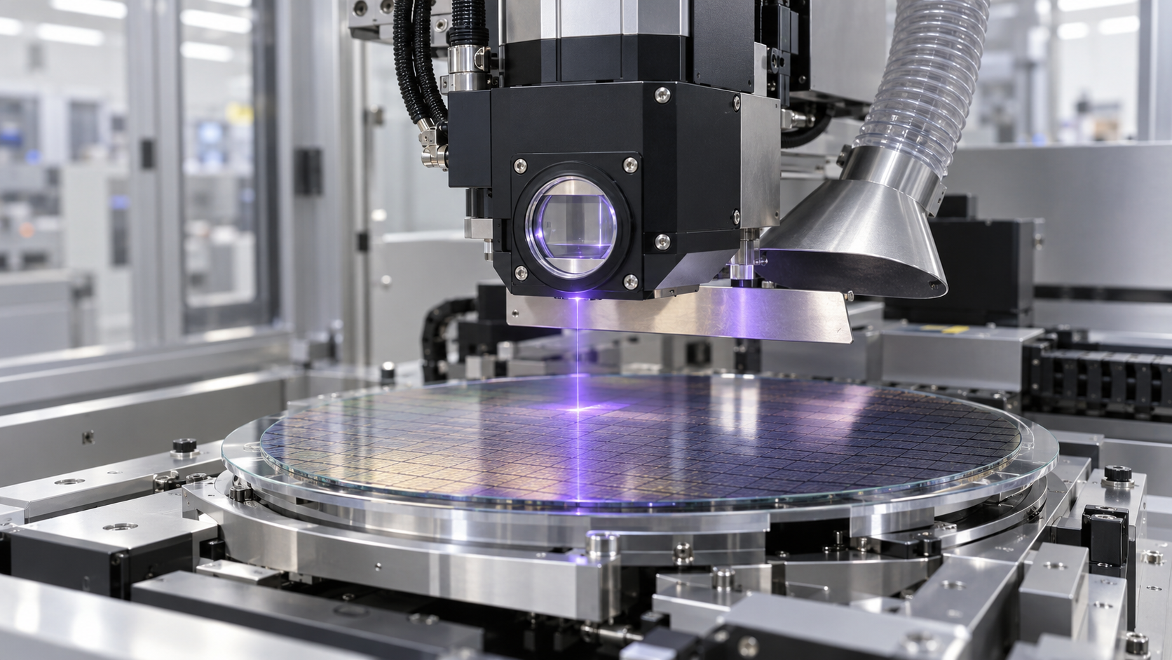
How Laser Debonding Supports HBM Manufacturing
HBM devices stack multiple thin DRAM dies vertically to reduce signal distance and increase memory bandwidth. As the number of dies per stack increases, individual dies must become thinner while maintaining sufficient mechanical integrity for handling, bonding and testing.
Temporary carrier systems support wafers during thinning and subsequent processing.
A simplified process may include:
- Bonding the device wafer to a temporary carrier
- Back grinding and thinning the device wafer
- Stress-relief polishing or etching
- TSV reveal and backside processing
- Redistribution-layer or pad formation
- Inspection and metrology
- Permanent bonding or die preparation
- Debonding from the temporary carrier
- Cleaning and final inspection
The exact sequence depends on the HBM architecture and whether the process uses wafer-to-wafer, die-to-wafer or other integration methods.
Laser debonding can provide a controlled, low-force release method that reduces the mechanical stress applied to ultra-thin wafers.
How Laser Debonding Relates to Hybrid Bonding
Hybrid bonding creates direct connections between dielectric surfaces and embedded metal pads, typically copper. It eliminates conventional solder bumps and supports much smaller interconnect pitches.
Temporary bonding and laser debonding may support a hybrid-bonding process, but they are not the same operation.
Hybrid bonding is the permanent joining step. Laser debonding removes a temporary carrier or releases a thin layer at another point in the manufacturing flow.
Not every hybrid-bonding process uses UV laser debonding. Alternative methods include:
- Mechanical debonding
- Thermal slide-off
- Chemical release
- IR laser release through silicon
- Other proprietary layer-transfer methods
The protective window must therefore be specified for the laser and process architecture actually installed in the equipment.
Three Components That Must Not Be Confused
A UV laser debonding system may include three optically different components.
1. Transparent Carrier
The carrier supports the fragile device wafer during processing. It may be made from glass, fused silica or another material compatible with the bonding and release process.
The carrier must satisfy requirements such as:
- Wafer-size compatibility
- Thickness and TTV
- Flatness and bow
- Hőtágulás
- UV transmission
- Kémiai összeférhetőség
- Bonding-layer adhesion
- Edge geometry
- Cleanroom cleanliness
2. Laser Release Layer
The release layer absorbs the selected wavelength and undergoes a controlled physical or chemical change. Its absorption, thickness and decomposition behavior determine the required laser fluence.
3. Protective Optical Window
The protective window isolates expensive beam-delivery optics from particles, vapors and residues generated near the process zone.
Its primary requirements include:
- High transmission at 355 nm
- Low wavefront distortion
- High laser-damage resistance
- Stable AR coating
- Low scatter
- Easy cleaning or replacement
- Resistance to repeated exposure and contamination
A sapphire window may be suitable for this third function even when the temporary carrier is made from another material.
Why 355 nm Is Used
A wavelength of 355 nm is commonly generated by frequency tripling a 1064 nm solid-state laser. It is widely used in semiconductor micromachining because it offers:
- Higher photon energy than visible or infrared lasers
- A relatively small focused spot
- Compatibility with many UV-absorbing release layers
- Mature beam-scanning optics
- Precise energy delivery
- Reduced heat-affected zones compared with some longer wavelengths
The laser may operate with nanosecond, picosecond or other pulse durations. Pulse energy, repetition rate, beam profile, scanning speed and spot overlap all affect the release process.
It is therefore insufficient to specify only “355 nm laser.”
The protective window supplier also needs to know:
- Impulzusidő
- Impulzusenergia
- Ismétlési arány
- Beam diameter at the window
- Beam shape
- Peak fluence
- Átlagos teljesítmény
- Polarizáció
- Incidence angle
- Expected contamination level
Can Sapphire Transmit 355 nm?
High-quality synthetic sapphire can transmit 355 nm ultraviolet light. Its useful transmission range extends from the UV into the mid-infrared, although actual performance depends on grade, purity, thickness, crystal orientation, surface finish and coating.
At 355 nm, bulk absorption in a suitable optical-grade sapphire window can be low enough for many protective-window applications.
However, total transmission is not determined by absorption alone. Sapphire has a relatively high refractive index, so an uncoated window reflects a significant amount of light at each air-to-sapphire interface.
An uncoated sapphire window may therefore transmit noticeably less energy than expected from bulk absorption data alone.
A wavelength-specific AR coating is usually considered when:
- Laser efficiency is important
- Energy calibration must remain stable
- Ghost reflections could affect the scanner
- Back-reflected energy could reach the laser source
- The process has a narrow fluence window
- The window has two polished parallel surfaces
Sapphire vs UV-Grade Fused Silica
Sapphire is not universally superior to UV-grade fused silica. The correct material depends on the equipment environment.
| Selection factor | Zafír | UV-grade fused silica |
|---|---|---|
| Transmission at 355 nm | Good with suitable grade and coating | Kiváló |
| Surface hardness | Nagyon magas | Alsó |
| Karcállóság | Kiváló | Mérsékelt |
| Hővezető képesség | Magasabb | Alsó |
| Hőtágulás | Higher and anisotropic | Very low |
| A kettőstörés | Intrinsic crystal birefringence | Very low in high-quality material |
| Törésmutató | Magasabb | Alsó |
| Uncoated surface reflection | Magasabb | Alsó |
| Precision polishing | More difficult | Generally easier |
| Harsh-environment durability | Kiváló | Jó |
| Költségek | Usually higher | Often lower |
Sapphire is attractive when the protective window faces repeated cleaning, particles, mechanical contact or higher thermal loading.
UV-grade fused silica may be preferred when very low birefringence, excellent UV homogeneity or minimum wavefront distortion is the dominant requirement.
The comparison should be made using coated components tested under the actual laser conditions.
What Laser-Induced Damage Threshold Means
Laser-induced damage threshold, commonly abbreviated as LIDT, describes the power or energy density at which an optical component begins to suffer irreversible laser damage under defined test conditions.
LIDT is not a single permanent material constant.
The result depends on:
- Wavelength
- Impulzusidő
- Pulse repetition rate
- A sugár átmérője
- Spatial beam profile
- Number of pulses
- Test method
- Felületi minőség
- Coating design
- Substrate absorption
- Szennyeződés
- Measurement definition
For pulsed lasers, fluence is commonly expressed in joules per square centimeter:
[
F=\frac{E}{A}
]
Hol:
- (F) is laser fluence
- (E) is pulse energy
- (A) is illuminated area
This simplified calculation does not account for a Gaussian beam’s local peak, pulse-to-pulse variation or overlapping pulses during scanning.
The latest LIDT test request should identify the applicable ISO 21254 method and operating parameters instead of stating only a value such as “greater than 5 J/cm².”
Why 355 nm Is Demanding for Optical Windows
Shorter wavelengths generally make laser systems more sensitive to surface defects and contamination.
At 355 nm:
- Small particles can absorb UV energy
- Organic residues may carbonize
- Coating nodules can initiate damage
- Polishing defects can concentrate the electric field
- Hydrocarbon films may increase absorption
- Repeated pulses can produce incubation effects
- Beam overlap can increase accumulated exposure
A window that survives a clean laboratory LIDT test may fail earlier inside production equipment if release debris gradually accumulates on its process-facing surface.
The qualification plan must therefore consider both initial LIDT and contaminated-window behavior.
Substrate Damage vs Coating Damage
Laser damage may begin in different parts of the optical component.
Bulk Damage
Bulk damage originates inside the sapphire. It may be associated with:
- Inclusions
- Internal defects
- Impurities
- Local absorption
- Excessively high peak intensity
Surface Damage
Surface damage begins at or near the polished surface. Causes can include:
- Scratches
- Garázsok
- Polishing residue
- A felszín alatti károsodás
- Edge defects
- Részecskék
- Ujjlenyomatok
Coating Damage
The AR coating is frequently the most damage-sensitive part of the finished window.
Coating damage can result from:
- Absorbing defects
- Nonuniform film thickness
- Szennyeződés
- Poor adhesion
- Excessive electric-field intensity
- Thermal expansion mismatch
- Incorrect cleaning
- Repeated UV exposure
The LIDT of the finished coated window—not only the uncoated sapphire substrate—should be verified.
Establishing an Operating Margin
A laser system should not operate continuously at the reported LIDT value.
The production limit should include a safety margin for:
- Laser-output variation
- Beam hot spots
- Focus shift
- Scan overlap
- Coating aging
- Window contamination
- Temperature changes
- Alignment errors
- Measurement uncertainty
The appropriate margin depends on the equipment’s reliability target and cost of failure.
In high-volume HBM production, gradual window damage can be particularly costly because it may change delivered fluence before the damage becomes visibly obvious. This can create incomplete release, local overheating or wafer breakage.
Selecting an AR Coating for 355 nm
A 355 nm AR coating should be specified using more than a center wavelength.
The RFQ should define:
- Operating wavelength and tolerance
- Beesési szög
- Angular scan range
- Polarizációs állapot
- Maximum reflectance per surface
- Average transmission
- Impulzusidő
- Peak fluence
- Ismétlési arány
- Átlagos teljesítmény
- Required LIDT test
- Környezeti tartósság
- Tisztítási módszer
- Process-facing surface
- Coating-free edge or mounting zone
For a fixed beam near normal incidence, a narrowband V-coating may provide very low reflectance.
For a scanning system, the angle of incidence can change as the beam moves across the wafer. A coating optimized only at zero degrees may produce increasing reflection and polarization dependence at larger scan angles.
The coating design must therefore match the full working angular range.
Polarization and Crystal Orientation
Sapphire is birefringent. Crystal orientation can influence the polarization state and wavefront of a laser passing through the window.
C-plane sapphire is usually a practical starting point when:
- The beam is close to normal incidence
- Polarization must remain stable
- The window is used in a scanning or imaging system
- Minimum unintended retardance is desired
However, a C-plane window used at oblique incidence can still introduce polarization-dependent behavior.
For a 355 nm scanning system, the optical design should consider:
- Sapphire crystal orientation
- Orientation tolerance
- Beam angle across the scan field
- Linear or circular polarization
- Coating response for S and P polarization
- Az ablak vastagsága
- Temperature-dependent birefringence
The supplier drawing should clearly state the selected sapphire plane.
Surface Quality and Subsurface Damage
Laser-grade polishing is more demanding than cosmetic polishing.
Visible scratches are important, but microscopic subsurface damage can also lower the damage threshold. The polishing process should minimize:
- Grinding cracks
- Deep polishing defects
- Élek lepattogzása
- Embedded polishing compound
- Surface contamination
- Local roughness
Depending on laser conditions, specifications may include:
- 20-10 scratch-dig
- 10-5 scratch-dig
- Surface roughness below approximately 1 nm Ra
- Controlled edge chamfer
- Laser-quality cleaning
- Individual cleanroom packaging
Stricter cosmetic specifications increase manufacturing cost and should be selected according to beam size, fluence and clear-aperture requirements.
Flatness, Parallelism and Wedge
A protective window can affect the focused spot even when its transmission is high.
Important optical parameters include:
- Felület síkossága
- Transmitted wavefront distortion
- Párhuzamosság
- Ék
- Thickness variation
- Refractive-index uniformity
Parallel surfaces can generate ghost reflections or etalon effects. A small controlled wedge may redirect unwanted reflections away from sensitive optics.
However, wedge also creates beam deviation. In a precision scanning system, this deviation must be included in calibration.
The correct choice depends on whether the window is installed:
- Before the scanning optics
- After the scanner
- Before the focusing lens
- Near the wafer
- At normal or oblique incidence
The optical engineer should define the permitted beam displacement rather than selecting wedge only by convention.
Where the Sapphire Protective Window Is Installed
Possible locations include:
Laser-Head Exit Window
This window seals the beam-delivery head and protects internal mirrors, scanners and focusing optics.
Process-Chamber Window
A window may separate the clean optical path from the wafer-processing environment.
Replaceable Debris Shield
A less expensive replaceable window can be installed in front of a more precise optical assembly.
Sensor Protection Window
Monitoring cameras, autofocus sensors or energy detectors may require their own protective windows.
The closer the window is to the release interface, the greater its likely exposure to particles and vapors.
Where Debris Comes From
During laser release, the absorbing layer may undergo:
- Photochemical decomposition
- Localized heating
- Gas generation
- Delamination
- Fragmentation
- Carbonization
Additional contamination may come from:
- Temporary adhesive
- Edge residue
- Carrier coatings
- Wafer-handling materials
- Chamber particles
- Cleaning residues
Some reaction products remain trapped at the release interface, while others may escape near wafer edges or enter the surrounding process space.
Even a very thin contamination film can increase 355 nm absorption.
How Debris Reduces Window Lifetime
Debris can damage the window through several mechanisms:
- Reduced UV transmission
- Increased local absorption
- Localized surface heating
- Coating discoloration
- Laser hot-spot formation
- Increased scattering
- Beam-profile distortion
- Lower effective LIDT
This creates a reinforcing failure cycle:
- Debris increases absorption
- Absorption raises temperature
- Heating damages the coating
- Coating damage creates stronger absorption
- The damage area grows under repeated pulses
The window should therefore be replaced before it reaches obvious visible failure.
Debris-Control Methods
Purge Gas or Air Knife
A controlled clean-gas flow can reduce the movement of particles toward the window.
The flow should not disturb wafer positioning, spread contaminants across the carrier or affect sensitive processing surfaces.
Local Exhaust
An extraction nozzle can remove vapors and fine debris close to the release area.
Exhaust geometry must be designed to avoid nonuniform cooling or particle redeposition.
Sacrificial Window
A replaceable sacrificial window protects the more expensive sapphire component. It must still provide stable transmission and adequate LIDT.
If the sacrificial window is low quality, it can distort the beam and reduce the benefit of the main sapphire window.
Mechanical Shutter
A shutter can protect the window during loading, unloading, cleaning and non-laser process steps.
Increased Working Distance
Moving the window farther from the release interface can reduce contamination, although it may enlarge the required clear aperture and change optical geometry.
Angled Window Installation
A slight angle can direct back reflections away from the laser source and may reduce direct deposition. Beam displacement and polarization effects must be included in the design.
In-Situ Transmission Monitoring
A reference detector can monitor delivered or returned laser energy. Gradual transmission loss can then be separated from changes in laser output.
Monitoring Window Condition
Visual inspection alone is not sufficient for a production laser window.
A maintenance system may track:
- Initial transmission
- Transmission after each process batch
- Reflected power
- Beam-profile change
- Scattered light
- Window temperature
- Delivered fluence at the wafer
- Number of processed wafers
- Number of laser pulses
- Cleaning history
Replacement criteria can be based on:
- Maximum permitted transmission loss
- Maximum beam distortion
- Maximum reflected power
- Detected coating damage
- Uncorrectable process nonuniformity
- Scheduled pulse count
A stable replacement threshold is especially important when the debonding process has a narrow energy window between incomplete release and device damage.
Cleaning the Sapphire Window
Sapphire’s high hardness provides excellent scratch resistance, but the window and its coating can still be damaged by incorrect cleaning.
Recommended cleaning procedures should define:
- Approved solvent
- Wipe material
- Direction of wiping
- Particle blow-off method
- Maximum contact pressure
- Coating-side identification
- Maximum number of cleaning cycles
- Inspection illumination
- Post-clean transmission test
Dry wiping a debris-covered window may drag hard particles across the coating. Loose particles should normally be removed using an approved noncontact method before solvent wiping.
The coating supplier should confirm chemical compatibility with the cleaning process.
Cleanliness for Hybrid Bonding Environments
Hybrid bonding requires exceptionally clean and smooth bonding surfaces. Small particles can create unbonded areas, voids or local defects.
Although the laser protective window does not contact the bonding interface, a poor debris-control system can become a particle source inside the equipment environment.
The window assembly should therefore consider:
- Low-particle mounting hardware
- Cleanroom-compatible seals
- Low-outgassing materials
- Controlled cleaning
- Particle-free replacement
- Covered transport
- Individual cleanroom packaging
Window maintenance should not introduce more contamination than the component removes.
Typical Specification Starting Points
The following examples are starting points only and must be adjusted to the actual laser.
| Paraméter | Possible starting requirement |
|---|---|
| Anyag | High-purity optical-grade synthetic sapphire |
| Kristályorientáció | C-plane for near-normal polarization-sensitive use |
| Wavelength | 355 nm |
| Tiszta átmérő | Defined according to full scan field |
| Felületi minőség | 20-10 or 10-5 |
| Felületi érdesség | Approximately 1 nm Ra or better when required |
| Felület síkossága | λ/10 at a specified test wavelength |
| Transmitted wavefront | Defined across the clear aperture |
| Párhuzamosság | Based on allowable beam deviation |
| Ék | Controlled if required to suppress back reflection |
| AR coating | 355 nm, angle- and polarization-specific |
| Reflectance | Defined per surface and over the angular range |
| LIDT | Tested under defined pulse and beam conditions |
| Élek kialakítása | Precision chamfer without chips |
| Tisztítás | Laser-grade cleanroom cleaning |
| Csomagolás | Individually packed with coating-side protection |
A supplier should not guarantee a useful LIDT value unless the wavelength, pulse duration, beam size and testing method are provided.
Árajánlatkérés ellenőrzőlista
When requesting a custom sapphire protective window, provide:
- Application: UV laser debonding
- Packaging process: HBM, 3D DRAM or hybrid-bonding support flow
- Installation position
- Működési hullámhossz
- Impulzusidő
- Impulzusenergia
- Ismétlési arány
- Beam diameter at the window
- Sugárprofil
- Maximum fluence
- Átlagos teljesítmény
- Polarizáció
- Incidence-angle range
- Sapphire crystal orientation
- Diameter, thickness and tolerance
- Tiszta átmérő
- Felületi minőség
- Felületi érdesség
- Felület síkossága
- Transmitted wavefront requirement
- Parallelism or wedge
- AR-coating requirement
- Required LIDT test method
- Hőmérséklet-tartomány
- Exposure to adhesive vapor or particles
- Tisztítószerek
- Mounting and sealing method
- Required cleanroom packaging
- Transmission-inspection report
- Material and coating traceability
Gyakran ismételt kérdések
Is the sapphire protective window the same as the carrier wafer?
No. The carrier provides mechanical support for the device wafer. The protective window shields the laser-delivery optics or separates the optics from the process area.
Is sapphire always used for UV laser debonding carriers?
No. UV-transparent glass and other engineered carrier materials are commonly used. The carrier material depends on the bonding adhesive, release layer, thermal budget and equipment platform.
Can sapphire transmit a 355 nm laser?
Yes, suitable optical-grade sapphire can transmit 355 nm. Total performance depends on purity, thickness, surface finish, orientation and AR coating.
Is sapphire better than fused silica at 355 nm?
Not in every application. Sapphire offers superior hardness and mechanical durability, while UV-grade fused silica may offer lower birefringence and excellent UV optical quality.
Is LIDT a fixed property of sapphire?
No. It depends on wavelength, pulse duration, beam size, pulse count, surface condition, coating and test method.
Does the AR coating reduce laser-damage resistance?
A high-quality coating can provide excellent performance, but the coating may become the limiting part of the component. The LIDT of the finished coated window must be tested.
How often should the protective window be replaced?
Replacement should be based on measured transmission, beam quality, contamination, pulse count and process stability—not only elapsed time.
Does every hybrid-bonding process need laser debonding?
No. Laser debonding is one possible supporting process for temporary carrier removal or layer transfer. The selected debonding method depends on the complete integration flow.
Következtetés
UV laser debonding helps enable the thin-wafer processing required for HBM, 3D DRAM and some hybrid-bonding integration flows. A sapphire protective window can provide durable optical isolation between the 355 nm beam-delivery system and the contaminated process environment.
Its suitability depends on more than basic UV transparency.
The finished window must maintain low optical loss, controlled wavefront distortion and sufficient laser-damage resistance under the actual wavelength, pulse duration, beam profile, scan overlap and contamination conditions.
The AR coating, surface finish and cleanliness often determine real production lifetime more than the theoretical strength of bulk sapphire.
Most importantly, the protective window, transparent carrier and laser release layer must be specified as separate functional components. When these roles are clearly defined, sapphire windows can contribute to more stable laser fluence, longer optical-system life and more repeatable debonding performance.