
Sapphire is widely known as a durable optical window material, but its combination of electrical insulation, low dielectric loss, mechanical strength, thermal stability and vacuum compatibility also makes it useful in selected radio-frequency, microwave and millimeter-wave systems.
In these applications, however, a sapphire window cannot be specified only by diameter, thickness and optical surface quality. RF performance depends strongly on dielectric constant, dielectric loss tangent, crystal orientation, operating frequency, window thickness, field distribution, temperature and cooling conditions.
A sapphire disk that performs well at one microwave frequency may generate unacceptable reflection or heating at another frequency. Likewise, there is no single “maximum RF power” that applies to every sapphire window.
This guide explains the main parameters engineers should consider when specifying fenêtres en saphir for RF and microwave systems.
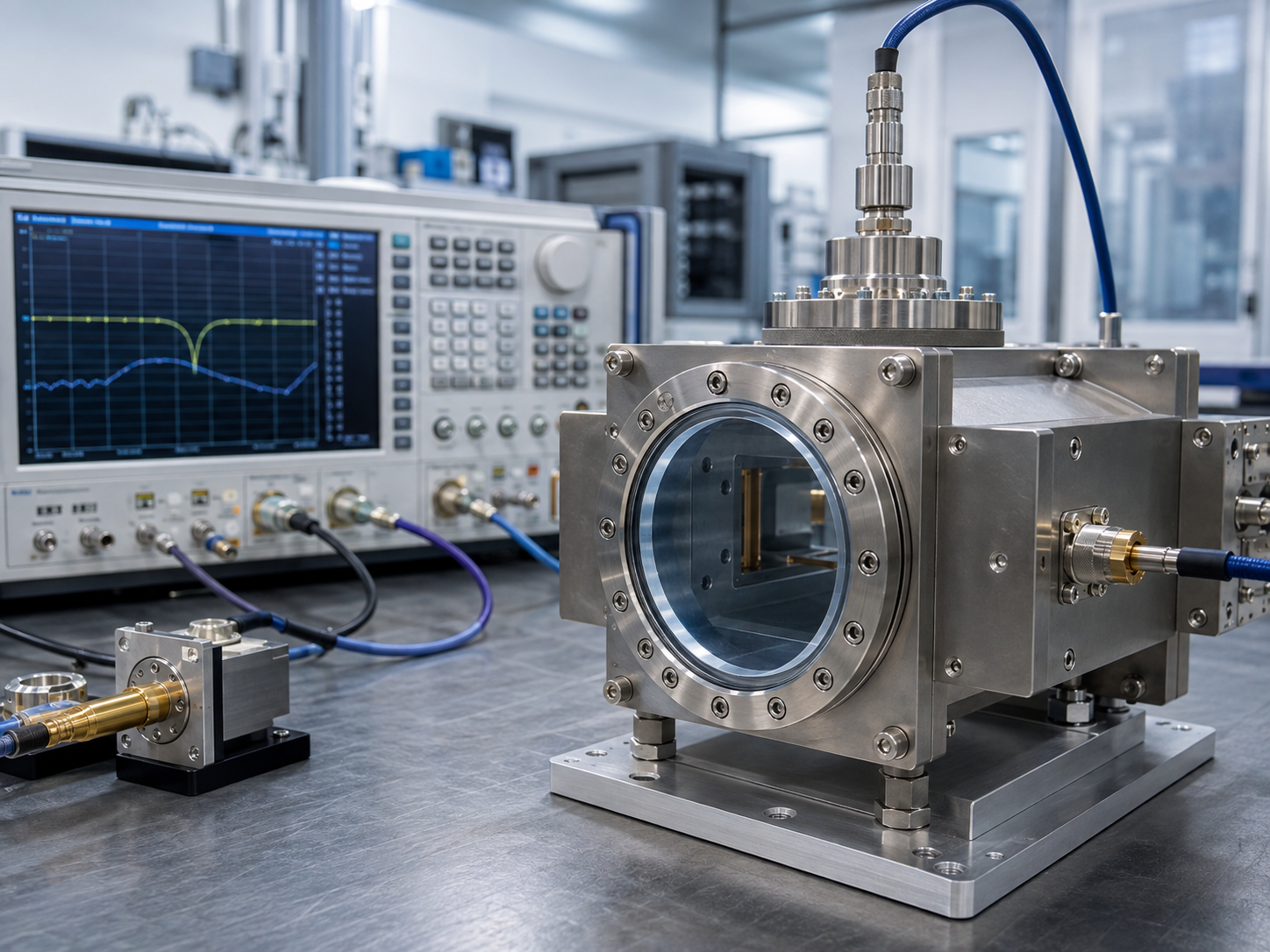
What Is an RF or Microwave Sapphire Window?
An RF window is a dielectric barrier that allows electromagnetic energy to pass while physically separating two environments.
Depending on the equipment, the window may separate:
- vacuum from atmosphere;
- two pressure regions;
- a microwave source from a transmission line;
- a plasma chamber from external RF hardware;
- a controlled gas environment from external components;
- a waveguide section from a vacuum device.
Unlike an ordinary optical viewport, its primary function may be the transmission of electromagnetic power rather than visible light.
Typical applications can include:
- microwave vacuum systems;
- gyrotron and microwave tube systems;
- RF plasma equipment;
- millimeter-wave research systems;
- dielectric resonators;
- high-frequency test equipment;
- scientific instrumentation;
- vacuum feedthrough assemblies.
The window therefore becomes part of the electromagnetic circuit.
Its dielectric properties must be included in RF simulations rather than treating the window simply as a mechanical cover.
1. Dielectric Constant of Sapphire
The relative dielectric constant, also called relative permittivity, determines how an electromagnetic field interacts with sapphire.
Sapphire is a single-crystal form of aluminum oxide, Al₂O₃, and it is anisotropic. This means its dielectric properties depend on the relationship between the electric field and the crystal axis.
Typical room-temperature reference values at relatively low frequency are approximately:
| Direction | Typical Relative Dielectric Constant |
|---|---|
| Parallel to the optical/c-axis | ~11.5 |
| Perpendicular to the optical/c-axis | ~9.4 |
These values are useful as general material references, but they should not automatically be used as exact microwave design values. Permittivity can vary with frequency, temperature, crystal quality and measurement direction.
This anisotropy is one reason crystal orientation should be specified for RF applications.
Why dielectric constant matters
A change in dielectric constant affects:
- electromagnetic wavelength inside the sapphire;
- phase delay;
- impedance matching;
- resonant frequency;
- reflection coefficient;
- transmission characteristics;
- electric-field distribution.
The wavelength inside a dielectric material is approximately:
λd = λ0 / √εr
where:
- λd = wavelength in the dielectric;
- λ0 = wavelength in free space;
- εr = relative dielectric constant.
Therefore, RF window thickness that appears mechanically insignificant can represent a substantial fraction of the electromagnetic wavelength at microwave or millimeter-wave frequencies.
2. Sapphire Is Anisotropic: Crystal Orientation Matters
For many ordinary protective optical windows, C-plane sapphire is selected primarily because of manufacturing availability and optical considerations.
For microwave systems, orientation can have an additional electrical consequence.
Because sapphire has different dielectric constants along different crystallographic directions, changing the orientation of the crystal relative to the RF electric field changes the effective permittivity seen by the electromagnetic wave.
This can influence:
- return loss;
- phase;
- resonance frequency;
- impedance;
- polarization behavior.
For narrow-band or resonant systems, even a relatively small deviation from the assumed dielectric properties can shift the optimum window condition.
An RF drawing should therefore specify the required sapphire orientation rather than simply stating:
Material: Sapphire
For critical designs, the RF engineer should define whether the electromagnetic field is predominantly parallel or perpendicular to the crystal c-axis.
3. What Is Dielectric Loss Tangent?
Relative permittivity describes how a dielectric stores electrical energy.
The loss tangent, commonly written as tan δ, indicates how much of that electromagnetic energy is dissipated in the material.
For RF window design:
lower tan δ generally means lower dielectric heating.
Sapphire can exhibit very low microwave dielectric loss, which is one reason high-quality single-crystal sapphire is also used in microwave resonators and precision frequency systems. NIST literature describes sapphire among the materials capable of extremely low microwave losses under appropriate conditions.
However, loss tangent should not be treated as one universal constant.
It may depend on:
- frequency;
- temperature;
- crystal purity;
- defects;
- impurities;
- crystal orientation;
- surface and interface condition;
- measurement technique.
Studies of low-loss dielectric materials also show that dielectric behavior can change with frequency, making it important to obtain frequency-appropriate data for demanding microwave designs.
4. Why Even Small Dielectric Loss Matters at High RF Power
At low test power, a small dielectric loss may appear insignificant.
At high transmitted power, the situation changes.
Consider a simplified example.
If an RF window absorbed only a very small percentage of the transmitted energy, that fraction may still represent substantial thermal power when the system carries tens or hundreds of kilowatts.
The resulting heat can create:
- center-to-edge temperature gradients;
- thermal expansion;
- localized thermal stress;
- changes in dielectric properties;
- changes in impedance matching;
- seal stress;
- cracking risk.
This is why high-power RF window design requires combined:
electromagnetic + thermal + structural analysis.
Published work on high-power microwave windows emphasizes that even small dielectric absorption can become a significant thermal problem as transmitted RF power increases.
5. Frequency Is a Critical Design Parameter
A sapphire window should never be specified for “microwave use” without specifying the operating frequency.
A design operating at:
- 2.45 GHz,
- 10 GHz,
- 24 GHz,
- 42 GHz,
- 94 GHz,
- 110 GHz,
- 170 GHz
does not see the same electrical thickness.
As frequency increases, free-space wavelength becomes shorter. This makes mechanical dimensional tolerances increasingly important relative to wavelength.
At millimeter-wave frequencies, relatively small changes in:
- sapphire thickness;
- air gap;
- mounting geometry;
- dielectric constant
can noticeably change S-parameters.
The frequency specification should therefore include:
- center frequency;
- operating bandwidth;
- single-frequency or multi-frequency operation;
- RF mode;
- polarization where relevant.
6. Window Thickness Is an RF Parameter, Not Only a Mechanical Parameter
For an ordinary pressure window, engineers may initially choose thickness from mechanical strength requirements.
For an RF window, this is not enough.
Thickness also controls electromagnetic interference between reflections from the two sapphire surfaces.
The incident wave is partially reflected at the first interface and again at the second interface. Depending on thickness and wavelength, these reflected components may reinforce or cancel each other.
As a result, certain thicknesses can produce:
- low reflection;
- high transmission;
while other thicknesses can produce:
- increased return loss;
- reduced transmission.
The optimum value therefore depends on:
frequency + dielectric constant + incidence geometry + surrounding medium.
For narrow-band RF systems, window thickness is often optimized using electromagnetic simulation.
A published 42 GHz gyrotron example used sapphire disks approximately 3.2 mm thick as part of a specially engineered double-disk RF window. This is an application-specific design rather than a general sapphire thickness recommendation.
That distinction is important.
A successful 42 GHz design should not simply be copied for another frequency.
7. Return Loss and Insertion Loss
Two important performance parameters are commonly evaluated during RF window design.
Return Loss
Return loss describes how much RF energy is reflected back toward the source.
High reflection can reduce transmitted power and can also create problems for sensitive microwave sources.
Window geometry is therefore optimized to minimize S11 at the required frequency.
Insertion Loss
Insertion loss describes how much signal or power is lost when the window is inserted into the RF path.
Loss can result from:
- dielectric absorption;
- reflections;
- mismatch;
- interfaces;
- additional cooling structures.
For high-power equipment, very small insertion losses may still create considerable heating.
For this reason, RF simulation and low-power network-analyzer testing are commonly used before high-power operation.
8. How Much RF Power Can a Sapphire Window Handle?
There is no meaningful universal answer such as:
“A sapphire window can handle X kW.”
Power capability depends on the complete assembly.
Important variables include:
- frequency;
- electromagnetic mode;
- beam diameter;
- electric-field distribution;
- sapphire diameter;
- thickness;
- loss tangent;
- dielectric constant;
- duty cycle;
- CW versus pulsed operation;
- pulse duration;
- cooling;
- mounting;
- braze or seal design;
- ambient pressure;
- vacuum load;
- temperature;
- edge stress.
Published microwave systems demonstrate the importance of this distinction.
For example, sapphire has been engineered into a double-disk window for a 42 GHz, 200 kW gyrotron, while other research systems have also used specially designed sapphire output windows at much higher frequencies. These achievements depend on carefully optimized electromagnetic, cooling and structural designs rather than on sapphire having a fixed intrinsic power rating.
For continuous-wave systems approaching very high average power, materials such as CVD diamond may be preferred because of their exceptionally high thermal conductivity and low microwave loss. Sapphire remains useful where its balance of RF properties, mechanical strength, optical transparency, availability and cost fits the system requirements.
9. CW and Pulsed Power Are Not Equivalent
A window rated successfully for a short pulse should not automatically be considered suitable for the same power under continuous operation.
Pulsed RF
Short pulses may produce very high peak electromagnetic fields while limiting total thermal energy deposited during each pulse.
Important parameters include:
- peak power;
- pulse duration;
- repetition rate;
- electric-field concentration.
Continuous-Wave RF
CW systems continuously deposit dielectric heat.
The design is therefore more sensitive to:
- loss tangent;
- thermal conductivity;
- cooling efficiency;
- temperature gradients;
- long-term thermal stress.
For RF window sourcing, the customer should always identify whether the specification refers to:
peak power or average power.
10. Temperature Changes RF Performance
Temperature matters in two ways.
First, sapphire expands as temperature rises.
Second, dielectric parameters can change with temperature.
These changes may shift:
- resonant frequency;
- electrical thickness;
- impedance;
- reflected power.
NIST research on electromagnetic window materials confirms that microwave permittivity can exhibit temperature dependence connected with material absorption mechanisms.
For narrow-band high-power systems, the RF window should therefore be evaluated at realistic operating temperature rather than only at room temperature.
11. Cooling and Mounting Design
As RF power rises, the sapphire disk can no longer be considered separately from its holder.
Possible cooling strategies include:
- edge cooling;
- gas cooling;
- liquid face cooling;
- double-disk cooling structures.
The selected method depends on frequency, transmitted power, window geometry and vacuum requirements.
Mounting must also accommodate sapphire’s thermal expansion without generating excessive edge stress.
A poorly designed mount can cause failure even when the sapphire itself has sufficient strength.
Particular attention should be paid to:
- edge clearance;
- braze geometry;
- metal coefficient of thermal expansion;
- sealing stress;
- clamping force;
- temperature gradients.
12. Surface Quality Still Matters
Although the RF performance is mainly controlled by dielectric and electromagnetic parameters, mechanical surface quality should not be ignored.
Surface and edge defects can reduce mechanical reliability under:
- vacuum load;
- pressure;
- thermal cycling;
- clamping;
- vibration.
Typical specifications may therefore include:
- surface polish;
- scratch-dig;
- flatness;
- parallelism;
- edge chamfer;
- edge chips;
- dimensional tolerance.
The importance of each specification depends on whether the same sapphire component must transmit both microwave energy and optical radiation.
13. RF Sapphire Window Specification Checklist
When requesting a custom sapphire RF or microwave window, providing the following information can significantly improve material selection and manufacturability evaluation.
Matériau
- Single-crystal sapphire
- Required purity or grade
Crystal
- C-plane, A-plane or other orientation
- Required orientation tolerance
Dimensions
- Diameter or length × width
- Épaisseur
- Tolérances dimensionnelles
- Ouverture effective
RF Requirements
- Center frequency
- Frequency range
- Microwave mode
- Polarisation
- Target S11 or return loss
- Target insertion loss
Puissance
- Peak RF power
- Average RF power
- CW or pulsed
- Pulse length
- Duty cycle
Environnement
- Niveau de vide
- Internal/external pressure
- Température de fonctionnement
- Cooling method
- Atmosphere or process gas
Mechanical Requirements
- Planéité
- Parallélisme
- Qualité de surface
- Edge specification
Assembly
- Metal housing material
- Brazed, bonded or mechanically clamped
- Seal configuration
- Cooling interface
Providing only diameter and thickness is usually insufficient for a high-power RF application.
Sapphire vs. Conventional Alumina for RF Windows
Sapphire and polycrystalline alumina have the same basic chemical composition, Al₂O₃, but their structures differ.
Sapphire is a single crystal.
This provides several potential advantages:
- absence of grain boundaries;
- excellent mechanical hardness;
- high chemical stability;
- optical transparency;
- controlled crystallographic orientation;
- low dielectric loss in appropriate frequency and temperature ranges.
The tradeoff is that sapphire is anisotropic, so orientation must be considered carefully in precision electromagnetic designs.
Conclusion
Sapphire can be an effective RF and microwave window material, but successful performance depends on much more than selecting a strong transparent ceramic.
The five most important parameters are:
dielectric constant, dielectric loss tangent, operating frequency, window thickness and RF power conditions.
Crystal orientation determines the effective dielectric response. Thickness controls electromagnetic interference and impedance matching. Loss tangent influences dielectric heating, while frequency and temperature affect the entire electrical design.
Most importantly, RF power handling is a property of the complete window system, not the sapphire disk alone.
For demanding RF, microwave and millimeter-wave applications, the recommended design process is:
define RF conditions → select sapphire orientation → establish dielectric data → optimize thickness electromagnetically → analyze thermal loading → evaluate structural stress → manufacture → verify S-parameters.
A complete RF specification allows the sapphire component to be designed as part of the electromagnetic system rather than treated as a conventional mechanical viewport.