
Silicon carbide manufacturing is moving from 150 mm wafers toward 200 mm production. Commercial 200 mm SiC epitaxy platforms are already available, including batch systems capable of processing multiple 200 mm wafers. At the same time, the successful demonstration of a single-crystal 300 mm SiC wafer in 2026 has opened discussion about how future crystal growth, epitaxy, inspection and advanced packaging equipment may evolve.
This transition affects more than wafer handling and chamber size. Larger wafers make temperature uniformity, film-thickness control, wafer bow, defect monitoring and process repeatability increasingly difficult. Epitaxy reactors therefore depend more heavily on in-situ optical monitoring.
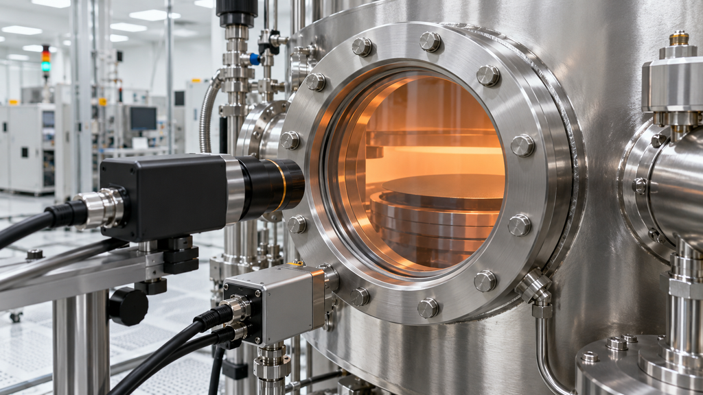
The optical viewport is a critical part of that measurement chain.
A sapphire viewport must transmit the selected pyrometry or reflectometry wavelength, withstand chamber pressure and thermal gradients, resist process deposits and maintain stable optical performance over repeated production runs.
This article explains how to specify sapphire viewports for current 200 mm and future 300 mm SiC epitaxy equipment without confusing bulk-material capability with actual installed-system performance.
Why Viewports Matter in SiC Epitaxy
SiC epitaxial layers are generally produced using high-temperature chemical vapor deposition processes. The reactor must maintain tight control over:
- Wafer temperature
- Radial temperature uniformity
- Gas-flow distribution
- Growth rate
- Epitaxial thickness
- Doping concentration
- Surface morphology
- Wafer bow and stress
- Run-to-run repeatability
Many of these parameters cannot be measured directly using sensors placed inside the hot process zone. Instead, optical instruments observe the wafer, susceptor or process emission through a viewport.
Typical optical functions include:
- Single-wavelength pyrometry
- Dual-wavelength or ratio pyrometry
- Multi-wavelength pyrometry
- Laser reflectometry
- Broadband reflectometry
- Optical emission monitoring
- Wafer-position monitoring
- Surface-temperature mapping
- Film-growth endpoint detection
- In-situ curvature or bow measurement
If the viewport changes transmission during a production run, the instrument may interpret that change as a change in wafer temperature or surface condition. Viewport performance is therefore part of process control, not merely a mechanical chamber requirement.
Why Sapphire Is Considered for Reactor Viewports
Synthetic sapphire combines several properties that are useful in harsh semiconductor equipment:
- High mechanical strength
- High surface hardness
- Good resistance to scratching
- Broad transmission from UV into the mid-infrared
- Good thermal conductivity compared with conventional optical glass
- High bulk-temperature capability
- Resistance to many process chemicals
- Good dimensional stability
- Availability in custom round, rectangular and stepped geometries
Sapphire may be considered where ordinary glass lacks adequate temperature, pressure or abrasion resistance.
However, sapphire is not automatically the best choice for every SiC reactor. The final selection should be based on:
- Monitoring wavelength
- Window temperature
- Process-gas chemistry
- Deposit composition
- Vacuum or pressure differential
- Required clear aperture
- Thermal-cycle profile
- Cleaning method
- Coating durability
- Allowed optical drift
- Total replacement cost
Quartz, fused silica and other optical materials may remain appropriate in some reactor designs. The selection should be made at the system level.
200 mm SiC Is Already an Equipment Requirement
The transition to 200 mm SiC is no longer only a laboratory target. Commercial epitaxy equipment supports both 150 mm and 200 mm processing, with some batch platforms handling six 200 mm wafers per run. SiC device manufacturers have also begun releasing products based on 200 mm manufacturing technology.
Moving from 150 mm to 200 mm increases the wafer area by approximately 78%. The reactor must maintain acceptable uniformity over a substantially larger surface while preserving throughput and yield.
For viewport and in-situ monitoring design, this can mean:
- A larger observation field
- Longer optical paths
- More off-axis measurements
- Multiple monitored positions
- Greater sensitivity to window wedge
- More stringent beam-position stability
- Increased thermal loading
- A larger deposition area
- More complex calibration
A window that performed adequately on a 150 mm reactor may not automatically satisfy a 200 mm tool, even if its diameter remains unchanged.
What Does “Future 300 mm SiC” Mean?
A single-crystal 300 mm SiC wafer was publicly demonstrated in 2026. This is an important materials milestone, but it does not mean that 300 mm SiC epitaxy has already entered high-volume manufacturing.
Current industrial planning should distinguish between:
- Production-ready 200 mm SiC equipment
- Research and pilot-scale 300 mm material development
- Future 300 mm epitaxy and wafer-processing infrastructure
- 300 mm SiC components proposed for advanced packaging applications
A 300 mm wafer has 2.25 times the area of a 200 mm wafer. Maintaining temperature, thickness and doping uniformity over this area will require more sophisticated chamber design and process monitoring.
Future 300 mm systems may need:
- Multiple pyrometry channels
- Radial temperature mapping
- Scanning optical heads
- Wider-field reflectometry
- Additional viewports
- More advanced window-transmission correction
- Higher repeatability in viewport replacement
- Improved deposit-management systems
The viewport does not necessarily need to become 50% larger simply because wafer diameter increases from 200 to 300 mm. In many cases, several smaller, well-positioned optical ports may provide better control than one very large window.
Selecting the Correct Pyrometry Wavelength
A pyrometer estimates temperature by measuring thermal radiation emitted from a surface. The selected wavelength strongly affects measurement accuracy.
There is no universal “best” pyrometry wavelength for every SiC epitaxy reactor. Selection depends on:
- Wafer temperature
- SiC doping and optical absorption
- Wafer thickness
- Surface emissivity
- Susceptor material
- Reactor geometry
- Background radiation
- Gas absorption
- Viewport transmission
- Deposit absorption
- Detector sensitivity
High-temperature processes produce sufficient radiation at visible and near-infrared wavelengths, allowing monitoring systems to use relatively short wavelengths that reduce sensitivity to certain background effects.
Wavelengths around the near-infrared region are frequently used for semiconductor temperature monitoring, but the final wavelength should be selected according to the actual wafer and reactor design.
A system may measure:
- Radiation from the SiC wafer surface
- Radiation transmitted through the wafer
- Radiation from the susceptor beneath the wafer
- A combination of wafer and susceptor signals
Because the optical properties of SiC vary with doping, thickness, crystal quality, temperature and wavelength, the measured signal does not always represent only the wafer surface.
Single-Wavelength vs Ratio Pyrometry
Single-wavelength pyrometry measures radiation intensity within a defined spectral band.
Its advantages include:
- Simple optical architecture
- High signal strength
- Fast response
- Relatively straightforward calibration
Its limitation is sensitivity to changes in emissivity and optical transmission. If a coating develops on the sapphire viewport, the pyrometer may report a lower temperature even when the actual wafer temperature remains unchanged.
Ratio pyrometry compares signals at two wavelengths. It can reduce sensitivity to some emissivity and transmission changes, but it is not automatically immune to viewport contamination.
The method becomes unreliable if:
- The deposit absorbs the two wavelengths differently
- Detector channels drift independently
- The wafer is not a gray-body emitter
- Reflections from the chamber change
- The two channels observe slightly different positions
- The sapphire coating has unequal spectral degradation
For this reason, viewport transmission should still be monitored and included in the calibration strategy.
Sapphire Transmission and Window Thickness
Sapphire transmits over a broad spectral range, but actual transmission depends on:
- Crystal purity
- اتجاه البلورة
- سمك النافذة
- Surface finish
- Internal defects
- درجة حرارة التشغيل
- Anti-reflection coating
- Incidence angle
- Surface contamination
A thicker viewport offers greater mechanical strength but also increases optical path length and material absorption.
Thickness selection must balance:
- مقاومة الضغط
- Clear-aperture diameter
- طريقة التركيب
- معامل الأمان
- الإرسال الضوئي
- Thermal-gradient stress
- Transmitted wavefront requirements
- Cost and manufacturing yield
The required thickness should be calculated using the actual pressure differential, unsupported diameter, edge support and temperature profile. A simple diameter-to-thickness rule is not sufficient for a safety-critical reactor viewport.
التوجه الكريستالي
C-plane sapphire is generally a practical starting point for optical viewports because light entering close to normal incidence travels approximately along the crystal optical axis. This can reduce unwanted birefringence compared with orientations where the optical axis is strongly inclined to the beam.
Crystal orientation becomes especially important when the viewport is used for:
- Polarized reflectometry
- Laser-based curvature measurement
- التداخل الضوئي
- Polarization-sensitive detection
- Oblique-incidence monitoring
For basic thermal-radiation collection, small polarization effects may be less important. For coherent laser metrology, they can produce phase error, beam displacement or fringe distortion.
A viewport drawing should specify the crystal plane and orientation tolerance instead of using only the general description “optical sapphire.”
Why Anti-Reflection Coatings Matter
Uncoated sapphire has significant Fresnel reflection at each surface. An anti-reflection coating can increase useful signal and reduce ghost reflections.
The coating must be designed for the actual monitoring system, including:
- Center wavelength
- Spectral bandwidth
- Incidence angle
- الاستقطاب
- Window temperature
- Cleaning chemistry
- Process exposure
- Laser power
- Required reflectance
- Coating lifetime
A broad “IR coating” specification is usually inadequate.
For example, a coating optimized for a near-normal 950 nm pyrometry channel may not perform correctly for an oblique reflectometry beam at another wavelength.
Coating durability may also become the limiting factor before the sapphire substrate itself reaches its thermal or chemical limit.
Deposit Buildup Is Often the Main Optical Failure Mode
In many epitaxy reactors, the sapphire does not fail mechanically. Instead, deposits gradually reduce or distort optical transmission.
Possible contaminants include:
- Silicon-containing deposits
- Carbon-rich films
- SiC-like coatings
- Process residues
- Condensed reaction by-products
- Particles released from chamber components
- Cleaning residues
Deposit buildup can cause:
- Lower transmitted intensity
- Spectral transmission changes
- Increased scattering
- Beam deflection
- Reduced image contrast
- Pyrometry offset
- Reflectometry amplitude loss
- Calibration drift
- False process alarms
A clean sapphire window and a partially coated sapphire window are not optically equivalent, even if both remain visibly transparent.
Why Deposit Transmission Cannot Be Treated as a Constant
A common correction method assumes that viewport contamination causes a fixed percentage loss.
In practice, deposit behavior may vary with:
- Film thickness
- Film composition
- درجة الحرارة
- Wavelength
- Position across the viewport
- Process recipe
- Number of runs
- Chamber-cleaning condition
A thin deposit may initially cause weak broadband attenuation. As it thickens, interference effects or wavelength-selective absorption can appear. The center and edge of the clear aperture may also accumulate material at different rates.
As a result, one correction factor may not remain valid throughout the maintenance cycle.
Methods for Reducing Deposit Buildup
Several design strategies can extend viewport service life.
Viewport Purging
A controlled purge-gas flow creates a local barrier between the process atmosphere and the window.
The purge must be optimized carefully. Excessive flow can disturb the reactor gas distribution, while insufficient flow may provide little protection.
Important variables include:
- Purge-gas type
- Flow rate
- Injection angle
- Port geometry
- Distance from the process zone
- Interaction with chamber pressure
Recessed Optical Ports
Positioning the window away from the direct line of deposition can reduce coating buildup. However, a long recessed port may restrict the field of view or cause internal reflections.
Shutters
A mechanical shutter can protect the window when optical monitoring is not required. The shutter material and mechanism must tolerate the process environment without generating particles.
Replaceable Sacrificial Windows
A thin replaceable optical plate can protect the main pressure-bearing sapphire viewport. Its spectral behavior and thermal stability must still be included in the optical calibration.
Transmission Monitoring
A reference light source can measure the changing transmission of the complete optical path. The process-control software can then compensate for gradual attenuation within validated limits.
Recipe-Based Maintenance
Viewport cleaning or replacement can be scheduled by accumulated process time, recipe type or optical-transmission threshold rather than by visual inspection alone.
Correcting for Viewport Coating
Modern in-situ metrology systems may include automated correction for viewport coating. Such correction can improve long-term measurement stability, but it has limits.
A correction system should ideally determine whether signal loss comes from:
- The viewport
- The wafer
- The susceptor
- The detector
- Optical misalignment
- Process-plasma changes
- Deposit accumulation elsewhere in the optical path
If contamination produces strong scattering, nonuniform coating or beam steering, software correction may no longer be sufficient. Physical cleaning or window replacement becomes necessary.
The equipment specification should define:
- Maximum correctable transmission loss
- Warning threshold
- Replacement threshold
- Calibration procedure after replacement
- Acceptable channel-to-channel variation
- Reference measurement frequency
Thermal Stress in Sapphire Viewports
The sapphire substrate may have excellent high-temperature capability, but an installed viewport is a complete assembly consisting of:
- Sapphire window
- Metal housing or flange
- Seal
- Retaining structure
- الطلاء
- Adhesive or brazed joint, if used
The maximum operating temperature of the assembly is often limited by the seal, coating or mounting design rather than the sapphire itself.
Thermal stress can develop because:
- The process-facing surface becomes hotter than the exterior surface
- The center heats faster than the supported edge
- The metal flange expands differently from sapphire
- Retaining-ring preload changes with temperature
- Cooling gas creates localized gradients
- Deposits absorb radiation and form hot spots
- Heating and cooling rates are too rapid
Sapphire is strong in compression but sensitive to tensile stress and edge defects. A small chip or machining crack can become a fracture origin during thermal cycling.
Managing CTE Mismatch
Sapphire and common flange metals have different coefficients of thermal expansion. Stainless steel and aluminum generally expand more than sapphire, while selected low-expansion alloys may provide a closer match.
CTE mismatch can lead to:
- Radial compression
- Tensile edge stress
- Window bowing
- Seal extrusion
- تشويه بصري
- Fatigue during repeated cycling
- Sudden fracture
A reliable design should avoid rigidly locking the sapphire between metal surfaces.
Possible measures include:
- Compliant seals
- Controlled radial clearance
- Uniform perimeter support
- Flexible retaining structures
- Rounded seating edges
- Accurate flange flatness
- Controlled bolt torque
- Finite element analysis
- Thermal-cycle qualification
The sealing system must maintain vacuum or pressure integrity while allowing differential expansion.
Large Viewports Are More Difficult to Scale
As clear aperture increases, the unsupported sapphire area increases and the window becomes more sensitive to:
- Pressure-induced bending
- Thickness variation
- Thermal gradients
- Edge-support nonuniformity
- Coating nonuniformity
- Residual polishing stress
- Mounting distortion
- Manufacturing yield
For a future 300 mm reactor, using one very large observation window may create more optical and mechanical risk than using several smaller ports.
A multi-port architecture can provide:
- Center and edge temperature measurements
- Separate pyrometry and reflectometry channels
- Redundant monitoring
- Easier window replacement
- Lower pressure stress
- Reduced coating cost
The correct approach depends on chamber geometry and the required process-control map.
Optical Requirements for In-Situ Reflectometry
Reflectometry measures changes in reflected optical intensity as epitaxial layers grow. It can provide information about:
- Growth rate
- Layer thickness
- خشونة السطح
- Optical constants
- Interface formation
- Process repeatability
The viewport can introduce errors through:
- Front- and rear-surface reflections
- Wedge
- Etalon effects
- Surface contamination
- الانكسار البيريفيرينجي
- Beam clipping
- Thermal lensing
- Coating drift
For coherent or narrowband light, nearly parallel sapphire surfaces may create unwanted interference. A controlled wedge may be preferable in some systems, provided the resulting beam deviation is included in the optical design.
The choice between parallel and wedged surfaces should therefore be made according to the monitoring method rather than by using a standard catalog-window specification.
Transmitted Wavefront and Beam Position
For pyrometry, total transmitted energy may be more important than wavefront quality. For laser reflectometry, curvature measurement and imaging, transmitted wavefront distortion becomes critical.
Relevant specifications include:
- تسطيح السطح
- Transmitted wavefront distortion
- التوازي
- Wedge
- جودة السطح
- خشونة السطح
- الفتحة الصافية
- Crystal-axis tolerance
A window may have acceptable surface flatness but still deflect the beam because its two surfaces are not sufficiently parallel.
Larger wafers and longer optical paths amplify beam-position errors. Future 300 mm monitoring systems may therefore require tighter wedge and mounting-repeatability controls.
Typical Specification Starting Points
The following values are examples for discussion, not universal requirements.
| المعلمة | General reactor observation | Precision optical monitoring |
|---|---|---|
| Sapphire grade | Optical-grade synthetic sapphire | High-purity optical-grade sapphire |
| اتجاه البلورة | Defined C-plane preferred | C-plane with controlled axis tolerance |
| جودة السطح | 40-20 or 20-10 | 20-10 or 10-5 |
| خشونة السطح | Application-dependent polished finish | Ra approximately 1 nm or better when required |
| تسطيح السطح | λ/4 may be sufficient | λ/10 or tighter at a specified wavelength |
| التوازي | Controlled by field-of-view requirement | 1 arc minute or tighter |
| Transmitted wavefront | May not be critical | Must be specified over the clear aperture |
| الطلاء | Optional or wavelength-specific | Custom AR coating for the exact channels |
| الحافة | Ground with protective chamfer | Precision chamfer with defect inspection |
| Cleanliness | Clean handling | Cleanroom cleaned and individually packaged |
The final values must be determined from the actual pressure, temperature, wavelength, aperture and measurement accuracy.
Common Failure Modes
| Failure mode | Likely cause | Possible result |
|---|---|---|
| Gradual signal loss | Deposit buildup | Pyrometry drift |
| Sudden temperature offset | Coating damage or window contamination | Incorrect process control |
| Beam displacement | Wedge, mounting shift or thermal distortion | Reflectometry instability |
| Window cracking | Edge defect, thermal shock or excessive preload | Vacuum failure and tool downtime |
| Seal leakage | CTE mismatch or seal degradation | Process contamination |
| Ghost reflections | Parallel surfaces or unsuitable AR coating | Noisy optical signal |
| Local hot spot | Nonuniform absorbing deposit | Thermal stress and coating failure |
| Poor replacement repeatability | Inconsistent mounting or window geometry | Tool-to-tool calibration mismatch |
Cleaning and Maintenance
The cleaning method must remove deposits without damaging the sapphire surface or coating.
Potential cleaning approaches include:
- Approved solvent cleaning
- Chemical cleaning
- Plasma cleaning
- Controlled mechanical cleaning
- Replacement of a sacrificial window
- Complete viewport replacement
Sapphire hardness does not make the component immune to damage. Aggressive wiping can drag hard particles across the surface and create scratches. Coatings are often softer and more chemically sensitive than the sapphire substrate.
Maintenance procedures should specify:
- Allowed chemicals
- Wipe material
- Particle-removal method
- Maximum cleaning cycles
- Post-clean transmission test
- Coating inspection
- Leak test after reassembly
- Calibration requirements
Recommended RFQ Information
A sapphire viewport request for SiC epitaxy equipment should include:
- Reactor type and process description
- Current wafer size and future platform requirements
- Viewport location and function
- Process-facing and external temperatures
- Heating and cooling rates
- Pressure or vacuum range
- Process and cleaning gases
- Clear-aperture diameter
- External diameter and thickness
- Sapphire crystal orientation
- Orientation tolerance
- جودة السطح
- تسطيح السطح
- Parallelism or wedge
- Transmitted wavefront requirement
- Monitoring wavelengths
- Incidence angles
- Polarization requirements
- AR-coating specification
- Required transmission before and after environmental testing
- Flange and sealing method
- Leak-rate requirement
- Expected maintenance interval
- Cleanroom cleaning and packaging requirements
- Required inspection report and material traceability
Providing the pyrometer model or optical-channel wavelengths can help the viewport manufacturer propose a more suitable coating.
الأسئلة الشائعة
Is sapphire always better than fused quartz for SiC epitaxy viewports?
No. Sapphire offers excellent strength, hardness and thermal performance, but quartz may provide advantages for particular wavelengths, thermal-expansion conditions or costs. The complete process environment must be evaluated.
What pyrometry wavelength should be used through sapphire?
There is no universal wavelength. The correct choice depends on sapphire transmission, SiC emissivity, wafer transparency, temperature range, detector sensitivity and process background.
Can a 200 mm reactor viewport be reused in a 300 mm system?
Possibly, but not automatically. The future system may require a wider field of view, multiple measurement positions, different incidence angles or tighter beam-position tolerances.
Does the sapphire window need an AR coating?
Not always, but an AR coating can improve signal strength and reduce ghost reflections. It must be designed for the exact wavelength, incidence angle, temperature and process exposure.
How does viewport coating affect pyrometry?
Deposits reduce and sometimes spectrally alter transmitted radiation. The pyrometer may report an incorrect temperature unless the change is measured, corrected or removed.
Should the viewport be enlarged for 300 mm wafers?
Not necessarily. Multiple smaller optical ports may offer better thermal, mechanical and metrology performance than one oversized viewport.
What normally limits viewport temperature?
The installed assembly is commonly limited by the coating, seal, flange or mounting stress rather than by the bulk sapphire alone.
الخاتمة
The transition from 150 mm to 200 mm SiC manufacturing is increasing the importance of accurate in-situ temperature and film-growth monitoring. The first 300 mm SiC material demonstrations indicate a possible future direction, but 300 mm SiC epitaxy should still be treated as a forward-looking equipment challenge rather than an established production standard.
Sapphire viewports can provide durable optical access to high-temperature SiC epitaxy reactors, but successful performance depends on much more than sapphire purity and thickness.
Pyrometry wavelength, wafer emissivity, crystal orientation, AR coating, deposit buildup, thermal gradients, CTE mismatch, mounting stress and calibration strategy must all be evaluated together.
For future equipment, the objective should not simply be a larger window. The better approach is a stable optical interface that maintains known transmission, predictable wavefront behavior and reliable sealing throughout the complete process and maintenance cycle.