
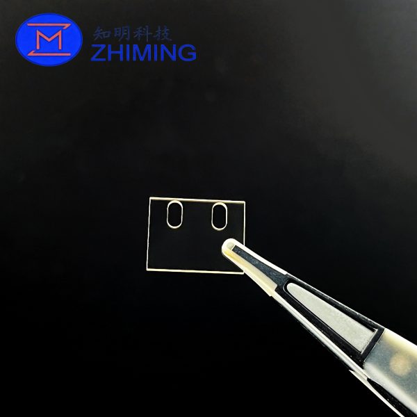
หน้าต่างแซฟไฟร์ with precision holes are used when an optical component must provide both environmental protection and a functional opening for a sensor, fiber, electrode, fastener, fluid channel or mechanical alignment feature. Compared with a conventional round or rectangular sapphire window, adding one or more holes significantly increases the difficulty of machining, polishing and inspection.
The challenge is not simply producing an opening through the sapphire. The manufacturer must control the hole diameter, hole position, taper, roundness, edge quality and remaining wall thickness without introducing cracks that could reduce the mechanical reliability of the finished window.
Single-crystal sapphire combines optical transparency with high hardness, heat resistance, chemical resistance and mechanical strength, making it suitable for demanding optical components and protective windows. However, its hardness also makes precision hole processing more difficult than machining many ordinary optical glasses.
For buyers, a successful sapphire window drawing should therefore define both the optical requirements of the window and the mechanical requirements of every hole.
Why Are Precision Holes Added to Sapphire Windows?
Holes in sapphire windows can perform different functions depending on the equipment design.
Common applications include:
- Openings for optical fibers or miniature probes
- Access holes for gas or liquid sampling
- Sensor alignment holes
- Electrical feedthrough clearances
- Mounting or fastening holes
- Pressure equalization ports
- Camera, laser or detector apertures
- Reference holes used during assembly
- Holes for thermocouples or measurement probes
- Multi-hole sapphire plates for analytical instruments
A hole may be located in the center of the window, offset from the optical axis or arranged as part of a multi-hole pattern. Some applications require a simple cylindrical through hole, while others require a counterbore, countersink, stepped hole, elongated slot or specially shaped opening.
Each design creates different machining and inspection requirements.
Hole Diameter Is More Than a Nominal Dimension
A drawing that only states “2 mm hole” does not provide enough information for precision manufacturing.
The hole specification should normally include:
- Nominal diameter
- Diameter tolerance
- Through-hole or blind-hole requirement
- Entrance diameter
- Exit diameter
- Allowable taper
- Roundness or circularity
- Hole-axis perpendicularity
- มุมเอียงหรือรัศมี
- Surface finish inside the hole
- Whether the hole intersects the optical clear aperture
For example, a nominal hole may be specified as:
Ø2.00 mm ±0.03 mm through hole
However, the achievable tolerance depends on several factors:
- ความหนาของแซฟไฟร์
- เส้นผ่านศูนย์กลางของรู
- อัตราส่วนความลึกต่อเส้นผ่านศูนย์กลางของรู
- จำนวนรู
- Distance from the hole to the outside edge
- Distance between neighboring holes
- Required edge quality
- Required internal wall finish
- วิธีการกลึง
- ปริมาณการผลิต
A small hole through a thick sapphire plate has a higher aspect ratio than the same hole through a thin window. Higher-aspect-ratio holes are generally more difficult to keep cylindrical because the entrance and exit dimensions may differ.
For this reason, buyers should not assume that a tight diameter tolerance automatically guarantees a straight hole. Taper and hole geometry should be evaluated separately.
Entrance Diameter, Exit Diameter and Hole Taper
Some sapphire drilling processes may produce a slightly larger opening on the entrance side than on the exit side. If the component is used only as a clearance plate, a small taper may be acceptable. If the hole positions a fiber, pin or sensor, taper can cause assembly problems.
The drawing can control this by defining:
- Maximum entrance diameter
- Maximum exit diameter
- Maximum difference between entrance and exit diameters
- Allowable taper angle
- Functional gauge requirements
For critical alignment applications, the customer should identify which side is the entrance side and which side is the optical or assembly reference surface.
When possible, the supplier should inspect the hole from both sides. Measuring only one opening does not confirm the geometry through the full thickness of the sapphire.
ความคลาดเคลื่อนของตำแหน่งรู
Hole position is especially important when the sapphire window must align with another component in a housing.
A hole location can be dimensioned from:
- The center of a round window
- Two perpendicular edges of a rectangular window
- A defined datum surface
- Another reference hole
- A mechanical flat
- The centerline of the optical clear aperture
A coordinate tolerance such as ±0.05 mm may be sufficient for some designs. More complex assemblies may require a true-position tolerance referenced to defined datums.
A proper drawing should clearly identify:
- Datum A: primary optical or mounting surface
- Datum B: outside diameter or reference edge
- Datum C: flat, secondary edge or reference hole
- Basic hole coordinates
- Positional tolerance zone
- Maximum material condition, when applicable
Without clear datums, the supplier and buyer may measure the same hole using different reference points and obtain different results.
For multi-hole sapphire components, true position is usually more useful than separately controlling every X and Y coordinate. It evaluates whether the hole axis falls inside an allowable cylindrical tolerance zone relative to the specified datums.
Concentricity Between a Hole and the Outside Diameter
A central hole in a round sapphire window is often assumed to be concentric with the outside diameter. However, “central” is not a measurable tolerance.
The drawing should state the allowable relationship between:
- Hole center
- Outside-diameter center
- Optical clear-aperture center
- Coating-aperture center
These centers may not always be identical.
For example, an optical system may require the hole to align with the optical aperture rather than the mechanical outside diameter. In another assembly, the outside diameter may be the primary locating feature.
The designer should identify which feature controls the final function.
Minimum Distance from the Hole to the Outer Edge
Placing a hole too close to the outside edge can leave a narrow sapphire ligament between the hole and the perimeter. This area may be vulnerable to cracking during machining, polishing, cleaning, coating, assembly or thermal cycling.
The minimum remaining wall should be evaluated based on:
- ความหนาของหน้าต่าง
- เส้นผ่านศูนย์กลางของรู
- Outside geometry
- Mounting load
- Internal pressure
- Edge support
- Thermal gradients
- Expected shock and vibration
- Acceptable edge chipping
There is no universal minimum wall thickness that applies to every sapphire component. A safe value for a low-load sensor cover may be unsuitable for a pressure window.
Customers should provide the supplier with the actual assembly conditions rather than selecting a wall thickness based only on appearance.
Edge Chipping Around Precision Holes
Edge chipping is one of the most important quality concerns for drilled sapphire windows.
Chips may occur around:
- Hole entrance edges
- Hole exit edges
- Intersections between holes and polished surfaces
- Counterbore shoulders
- Slots and sharp internal corners
- Areas with insufficient supporting material
ISO 10110 provides a standardized framework for indicating optical-component requirements on technical drawings. Its surface-imperfection provisions include localized imperfections, scratches and edge chips within the effective aperture.
A purchase drawing should distinguish between chipping inside the functional optical area and chipping outside it.
Important inspection zones may include:
- รูรับแสงThe area through which light must pass. Defects in this region can affect image quality, scattering or transmission.
- Hole functional edgeThe edge that contacts, locates or seals against another component.
- Non-functional edge zoneAn area hidden by a housing or mounting structure where slightly larger cosmetic defects may be acceptable.
- Bonding or sealing areaThe surface used for adhesive bonding, brazing, metallization or gasket sealing.
The buyer should specify the maximum permissible chip size, quantity and location rather than using a general statement such as “no chipping.”
Chamfers and Edge Radii
A controlled chamfer or radius can reduce sharp-edge damage and make the sapphire component easier to handle and assemble.
Possible specifications include:
- Protective chamfer on both sides
- Chamfer on the assembly side only
- Radius around the hole entrance
- Polished hole edge
- Fine-ground, non-polished hole edge
- Sharp edge with a controlled maximum break
A chamfer may also help prevent a fastener, seal or fiber from contacting a sharp sapphire corner.
However, chamfer size must be controlled. An oversized chamfer can reduce the available sealing surface, interfere with a mating component or enlarge the optical obstruction around the hole.
Machining Methods for Sapphire Holes
The selected processing route depends on hole size, thickness, tolerance, surface quality and production volume.
การกลึงด้วยเครื่องมือเพชร
Diamond grinding and related mechanical methods can be suitable for larger holes and certain dimensional requirements. The tooling, feed rate, cooling and support method must be carefully controlled to reduce chipping and subsurface damage.
Mechanical processing may also be combined with subsequent lapping or polishing.
การเจาะด้วยเลเซอร์
Laser drilling is useful for small holes, complex patterns and designs that are difficult to produce mechanically. Different laser parameters can produce different levels of taper, heat-affected material, redeposition and edge roughness.
Ultrafast laser processes are commonly investigated for transparent hard materials because short pulses can reduce thermal effects compared with longer-pulse processing. Research has demonstrated laser-based methods for producing high-quality holes in sapphire and other transparent hard materials, including hybrid processes combining laser modification with material removal.
The term “laser drilled” alone does not define the finished quality. The drawing should still specify the required diameter, taper, edge chipping and cleanliness.
Hybrid Processing
Some components use multiple processes, such as:
- Laser rough opening
- Diamond finishing
- Edge smoothing
- การขัดผิว
- การขัดเงาด้วยแสง
- Final cleaning and inspection
A hybrid process can improve dimensional control, but it may increase cost and lead time. It is usually selected when the functional requirements cannot be achieved reliably with one process alone.
Hole Quality and Optical Surface Quality Must Be Specified Separately
A sapphire window may have excellent polished faces but still contain unacceptable damage around the hole. Conversely, a well-drilled hole does not guarantee that the optical surfaces meet the required flatness or surface-quality specification.
The drawing should separately define:
Optical surfaces
- คุณภาพผิว
- ความหยาบของพื้นผิว
- ความเรียบ
- ความสมมาตร
- Wedge
- รูรับแสง
- ข้อกำหนดในการเคลือบ
Hole features
- เส้นผ่านศูนย์กลาง
- Position
- เทเปอร์
- Roundness
- Perpendicularity
- Internal surface condition
- การแตกขอบ
- Chamfer
- ความสะอาด
This separation makes inspection criteria clearer and reduces disagreements during incoming inspection.
Inspection Methods
A complete inspection plan may use several tools because no single method verifies every hole characteristic.
Optical Comparator or Vision Measuring System
Suitable for checking:
- Entrance and exit diameter
- ตำแหน่งรู
- Roundness
- การแตกขอบ
- ขนาดมุมตัด
- Multi-hole spacing
Machine-vision methods can also support repeatable assessment of optical surface imperfections when properly configured. ISO/TR 14997-2 provides guidance on machine-vision assessment of surface imperfections defined under ISO 10110-7.
Measuring Microscope
A measuring microscope can evaluate small hole features and local edge defects at higher magnification.
Pin Gauges
Pin gauges may be useful for functional acceptance of certain cylindrical holes. However, a passing pin does not fully verify position, taper or roundness.
The inspection force must also be controlled to avoid damaging the sapphire edge.
Coordinate Measuring Machine
A CMM may be used for larger features, hole patterns and positional relationships. The selected probe and measurement strategy must be suitable for the component dimensions and edge geometry.
Computed Tomography
Industrial CT can evaluate internal hole geometry, taper and concealed defects without sectioning the component. It may be appropriate for high-value or complex parts, although it is not normally required for every production order.
Visual and Dark-Field Inspection
Controlled illumination can reveal:
- ชิป Edge
- รอยแตก
- Scratches
- อนุภาค
- Residue
- Laser redeposition
- Localized surface damage
Magnification, illumination method and acceptance standards should be agreed before production.
Coating Considerations Around Holes
If the sapphire window requires an anti-reflection, conductive, protective or metallized coating, the customer should specify whether the coating must extend into the hole.
Possible requirements include:
- Coating on both major surfaces only
- Coating excluded from the hole wall
- Coating inside the hole
- Masked annular area around the hole
- Uncoated bonding or sealing region
- Maximum coating-edge overspray
Hole edges can make coating uniformity more difficult. A coating that enters the hole may alter the effective diameter or create an uneven boundary.
The drawing should therefore define the coating aperture and masking requirements separately from the mechanical hole diameter.
Recommended RFQ Information
To receive an accurate quotation, buyers should provide:
| RFQ Item | Information to Specify |
|---|---|
| Sapphire orientation | C-plane, A-plane, M-plane or other |
| รูปทรงของหน้าต่าง | Round, rectangular or custom |
| Outside dimensions | Diameter, length and width |
| ความหนา | Nominal value and tolerance |
| Hole type | Through, blind, stepped, counterbored or slotted |
| เส้นผ่านศูนย์กลางของรู | Nominal size and tolerance |
| Hole quantity | Number of holes per component |
| ตำแหน่งรู | Coordinates and datum references |
| เทเปอร์ | Maximum allowable entrance-to-exit variation |
| การแตกขอบ | Maximum size, quantity and inspection zone |
| Chamfer | Size, angle or radius |
| Hole-wall finish | As-machined, ground or polished |
| Optical surface quality | Scratch-dig or ISO requirement |
| ความเรียบ | Required over the full surface or clear aperture |
| Parallelism or wedge | Maximum allowable value |
| รูรับแสง | Usable optical area |
| การเคลือบ | Wavelength, reflectance and masked areas |
| ใบสมัคร | Sensor, vacuum, pressure, imaging or other |
| ปริมาณ | Prototype and production volume |
| รายงานการตรวจสอบ | Standard report, dimensional report or full inspection |
A 2D drawing in PDF format is useful for quotation, while a STEP file may be required for stepped holes, slots and complex three-dimensional features.
Common Drawing Mistakes
Frequent problems include:
- Giving a nominal hole diameter without tolerance
- Not identifying the entrance and exit sides
- Omitting the allowable hole taper
- Using the word “centered” without a measurable position tolerance
- Failing to define measurement datums
- Specifying “no chips” without an inspection limit
- Placing a hole too close to the outside edge
- Forgetting to define the clear aperture around the hole
- Not indicating whether the hole edge requires a chamfer
- Applying optical surface requirements to the hole wall without clarification
- Failing to define coating masking around the hole
- Requiring unnecessarily tight tolerances that increase cost without improving function
Resolving these issues before manufacturing can reduce engineering revisions, sample failures and inspection disputes.
สรุป
Sapphire windows with precision holes require coordinated control of optical performance and mechanical geometry. Hole diameter alone is not enough to define a manufacturable component.
A complete specification should cover hole position, entrance and exit dimensions, taper, edge chipping, chamfer, remaining wall thickness, clear aperture, coating boundaries and inspection methods.
The best results are achieved when the buyer provides a detailed drawing together with information about the final assembly, sealing method, pressure conditions and optical function. This allows the sapphire manufacturer to select an appropriate machining process and recommend tolerances that balance performance, reliability and cost.
คำถามที่พบบ่อย
Can sapphire windows be manufactured with multiple precision holes?
Yes. Multiple holes can be produced in a sapphire window, but the manufacturer must evaluate hole spacing, distance from the outside edge, window thickness and positional tolerances. Closely spaced holes can increase the risk of cracking or distortion.
Can the inside wall of a sapphire hole be polished?
Certain hole sizes and geometries can receive additional finishing, but polishing the internal wall is more difficult than polishing the two main optical surfaces. The required roughness and optical function should be discussed during the quotation stage.
How should edge chipping around a sapphire hole be specified?
The drawing should define the maximum chip size, permissible quantity and inspection area. It should also distinguish between the clear aperture, sealing surface, functional hole edge and non-functional mounting region.
Is laser drilling always suitable for small sapphire holes?
Laser drilling is often suitable for small or complex holes, but the final result depends on sapphire thickness, diameter, aspect ratio, taper and edge-quality requirements. Some demanding designs may require a hybrid laser and mechanical finishing process.